
Data Systems, Inc. Computer Hardware User Manual


PMAC2A PC104 Hardware Reference Manual
Software Setup
26
In order to properly setup the digital outputs an initialization PLC must be written scanning through once
on power-up/reset, then disabling itself:
OPEN PLC1 CLEAR
M32=$FF ;BITS 0-8 are assigned as output
M34=$0 ;BITS 9-16 are assigned as input
M40=$FF00 ;Define inputs and outputs voltages
M42=$FFFF ;All lines are I/O type
DIS PLC1 ;Disable PLC1 (scanning through once on
;power-up/reset)
CLOSE
Note:
After loading this program, set I5=2 or 3 and ENABLE PLC 1.
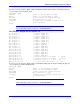
Acc-2P with Jumper E5 in Position 2-3
M0->Y:$C0C0,0 ; Digital Output M00
M1->Y:$C0C0,1 ; Digital Output M01
M2->Y:$C0C0,2 ; Digital Output M02
M3->Y:$C0C0,3 ; Digital Output M03
M4->Y:$C0C0,4 ; Digital Output M04
M5->Y:$C0C0,5 ; Digital Output M05
M6->Y:$C0C0,6 ; Digital Output M06
M7->Y:$C0C0,7 ; Digital Output M07
M8->Y:$C0C0,8 ; Digital Input MI0
M9->Y:$C0C0,9 ; Digital Input MI1
M10->Y:$C0C0,10 ; Digital Input MI2
M11->Y:$C0C0,11 ; Digital Input MI3
M12->Y:$C0C0,12 ; Digital Input MI4
M13->Y:$C0C0,13 ; Digital Input MI5
M14->Y:$C0C0,14 ; Digital Input MI6
M15->Y:$C0C0,15 ; Digital Input MI7
M32->X:$C0C0,0,8 ; Direction Control (1=output, 0 = input)
M34->X:$C0C0,8,8 ; Direction Control (1=output, 0 = input)
M40->X:$C0C4,0,24 ; Inversion control (0 = 0V, 1 = 5V)
M42->Y:$C0C4,0,24 ; JI/O port data type control (1 = I/O)
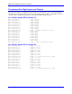
In order to properly setup the digital outputs, an initialization PLC must be written scanning through once
on power-up/reset, and then disabling itself:
OPEN PLC1 CLEAR
M32=$FF ;BITS 0-8 are assigned as output
M34=$0 ;BITS 9-16 are assigned as input
M40=$FFFF ;Define inputs and outputs voltages
M42=$FFFF ;All lines are I/O type
DIS PLC1 ;Disable PLC1 (scanning through once on
;power-up/reset)
CLOSE
Note:
After loading this program, set I5=2 or 3 and ENABLE PLC 1.