
Data Systems, Inc. Computer Hardware User Manual

PMAC2A PC104 Hardware Reference Manual
Base Board Connector Pinouts
52
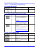
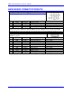
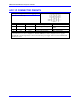
J4 (JMACH2): Machine Port Baseboard
Connector
(34-Pin Header)
Front View
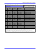
Pin# Symbol Function Description Notes
1 FLG_1_2_V Input Flags 1-2 Pull-Up
2 FLG_3_4_V Input Flags 3-4 Pull-Up
3 GND Common Digital Common
4 GND Common Digital Common
5 HOME1 Input Home-Flag 1 10
6 HOME2 Input Home-Flag 2 10
7 PLIM1 Input Positive End Limit 1 8,9
8 PLIM2 Input Positive End Limit 2 8,9
9 MLIM1 Input Negative End Limit 1 8,9
10 MLIM2 Input Negative End Limit 2 8,9
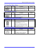
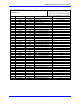
11 USER1 Input User Flag 1
12 USER2 Input User Flag 2
13 PUL_1 Output Pulse Output 1
14 PUL_2 Output Pulse Output 2
15 DIR_1 Output Direction Output 1
16 DIR_2 Output Direction Output 2
17 EQU1 Output Encoder Comp-Equal 1
18 EQU2 Output Encoder Comp-Equal 2
19 HOME3 Input Home-Flag 3 10
20 HOME4 Input Home-Flag 4 10
21 PLIM3 Input Positive End Limit 3 8,9
22 PLIM4 Input Positive End Limit 4 8,9
23 MLIM3 Input Negative End Limit 3 8,9
24 MLIM4 Input Negative End Limit 4 8,9
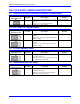
25 USER1 Input User Flag 1
26 USER2 Input User Flag 2
27 PUL_3 Output Pulse Output 3
28 PUL_4 Output Pulse Output 4
29 DIR_3 Output Direction Output 3
30 DIR_4 Output Direction Output 4
31 EQU3 Output Encoder Comp-Equal 3
32 EQU4 Output Encoder Comp-Equal 4
33 B_WDO Output Watchdog Out Indicator/driver
34 No Connect
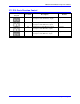
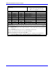
Note 1: Pins marked PLIMn should be connected to switches at the positive end of travel. Pins marked MLIMn
should be connected to switches at the negative end of travel.
Note 2: Must be conducting to 0V (usually GND) for PMAC to consider itself not into this limit. Automatic limit
function can be disabled with Ix25.
Note 3: Functional polarity for homing or other trigger use of HOMEn controlled by Encoder/Flag Variable I9n2.
HMFLn selected for trigger by Encoder/Flag Variable I9n3. Must be conducting to 0V (usually GND) to
produce a 0 in PMAC software.