^1 HARDWARE MANUAL ^2 PMAC2A-PC/104 ^3 Compact Version of PMAC Family ^4 4xx-603670-xHxx ^5 November 6, 2003 Single Source Machine Control Power // Flexibility // Ease of Use 21314 Lassen Street Chatsworth, CA 91311 // Tel. (818) 998-2095 Fax. (818) 998-7807 // www.deltatau.
Copyright Information © 2003 Delta Tau Data Systems, Inc. All rights reserved. This document is furnished for the customers of Delta Tau Data Systems, Inc. Other uses are unauthorized without written permission of Delta Tau Data Systems, Inc. Information contained in this manual may be updated from time-to-time due to product improvements, etc., and may not conform in every respect to former issues. To report errors or inconsistencies, call or email: Delta Tau Data Systems, Inc.
PMAC2A-PC104 Hardware Manual Table of Contents INTRODUCTION .......................................................................................................................................................1 Overview ...................................................................................................................................................................1 Board Configuration.........................................................................................................
PMAC2A-PC104 Hardware Manual Incremental Encoder Connection .......................................................................................................................15 DAC Output Signals ...........................................................................................................................................15 Pulse and Direction (Stepper) Drivers ...............................................................................................................
PMAC2A-PC104 Hardware Manual Board Layout...........................................................................................................................................................38 Connectors and Indicators .......................................................................................................................................39 J1 – USB Communications Port .......................................................................................................................
PMAC2A-PC104 Hardware Manual iv Table of Contents
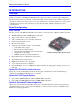
PMAC2A-PC104 Hardware Manual INTRODUCTION Overview The PMAC2A-PC/104 motion controller is a compact, cost-effective version of the Delta Tau’s PMAC2 family of controllers. The PMAC2A-PC/104 can be composed of three boards in a stack configuration. The baseboard provides four channels of either DAC ±10V or pulse and direction command outputs. The optional axis expansion board provides a set of four additional servo channels and I/O ports.
PMAC2A-PC104 Hardware Manual Option 6L: Multi-block Lookahead Firmware Option 6L provides a special lookahead firmware for sophisticated acceleration and cornering profiles execution. With the lookahead firmware PMAC automatically controls the speed along the path (but without changing the path) to ensure that axis limits are not violated. Option 10: Firmware Version Specification Normally the PMAC PCI-Lite is provided with the newest released firmware version.
PMAC2A-PC104 Hardware Manual ACC-2P: Communications Board Without any options, the PMAC2A-PC/104 communicates through the RS-232 serial interface using the optional ACC-3L flat cable. Only one method of communication is allowed at a time. ACC-2P Option 1A: USB Interface Option 1A it provides a 12 Mbit/sec USB interface allowing USB communications with the PMAC2APC/104 motion controller.
PMAC2A-PC104 Hardware Manual 4 Introduction
PMAC2A-PC104 Hardware Manual BASE BOARD HARDWARE SETUP On the PMAC2-PC/104 baseboard, you will see many jumpers (pairs of metal prongs), called E-points or W-points. Some have been shorted together; others have been left open. These jumpers customize the hardware features of the baseboard for a given application and must be setup appropriately. The following is an overview of the several jumpers grouped in appropriate categories.
PMAC2A-PC104 Hardware Manual E13: Firmware Load Jumper – If jumper E13 is ON during power-up/reset, the board comes up in “bootstrap mode”, which permits the loading of new firmware into the flash-memory IC on the board. When the PMAC Executive program tries to establish communications with a board in this mode, it will automatically detect that the board is in bootstrap mode and ask you what file you want to download as the new firmware.
PMAC2A-PC104 Hardware Manual Resistor Packs Configuration Differential or Single-Ended Encoder Selection The differential input signal pairs to the PMAC have user-configurable pull-up/pull-down resistor networks to permit the acceptance of either single-ended or differential signals in one setting, or the detection of lost differential signals in another setting. The ‘+’ inputs of each differential pair each have a hard-wired 1 kΩ pull-up resistor to +5V. This cannot be changed.
PMAC2A-PC104 Hardware Manual 8 Baseboard Hardware Setup
PMAC2A-PC104 Hardware Manual ACC-1P HARDWARE SETUP On the ACC-1P, you will see many jumpers (pairs of metal prongs), called E-points. Some have been shorted together; others have been left open. These jumpers customize the hardware features of the ACC1P for a given application and must be setup appropriately. The following is an overview of the several jumpers grouped in appropriate categories.
PMAC2A-PC104 Hardware Manual The ‘-‘ inputs of each differential pair each have a hard-wired 2.2 kΩ resistor to +5V; each also has another 2.2 kΩ resistor as part of a socketed resistor pack that can be configured as a pull-up resistor to +5V, or a pull-down resistor to GND. If this socketed resistor is configured as a pull-down resistor (the default configuration), the combination of pull-up and pull-down resistors on this line acts as a voltage divider, holding the line at +2.
PMAC2A-PC104 Hardware Manual ACC-2P HARDWARE SETUP On the ACC-2P, you will see many jumpers (pairs of metal prongs), called E-points. Some have been shorted together; others have been left open. These jumpers customize the hardware features of the ACC2P for a given application and must be setup appropriately. The following is an overview of the several jumpers grouped in appropriate categories.
PMAC2A-PC104 Hardware Manual If this socketed resistor is configured as a pull-down resistor (the default configuration), the combination of pull-up and pull-down resistors on this line acts as a voltage divider, holding the line at +2.5V in the absence of an external signal. This configuration is required for single-ended inputs using the ‘+’ lines alone; it is desirable for unconnected inputs to prevent the pick-up of spurious noise; it is permissible for differential line-driver inputs.
PMAC2A-PC104 Hardware Manual MACHINE CONNECTIONS Typically, the user connections are actually made to terminal blocks that are attached to the JMACH connectors by a flat cable.
PMAC2A-PC104 Hardware Manual DAC Outputs Power Supply 0.3A @ +12 to +15V (4.5W) 0.25A @ -12 to -15V (3.8W) (Eight-channel configuration) • • The host computer provides the ±12 Volts power supply in the case PMAC is installed in the PC/104 bus. With the board stack into the bus, it will automatically pull ±12V power from the bus and it cannot be disconnected. In this case, there must be no external ±12V supply, or the two supplies will "fight" each other, possibly causing damage.
PMAC2A-PC104 Hardware Manual Motor Signals Connections Incremental Encoder Connection Each JMACH1 connector provides two +5V outputs and two logic grounds for powering encoders and other devices. The +5V outputs are on pins 1 and 2; the grounds are on pins 3 and 4. The encoder signal pins are grouped by number: all those numbered 1 (CHA1+, CHA1-, CHB1+, CHC1+, etc.) belong to encoder #1. The encoder number does not have to match the motor number, but usually does.
PMAC2A-PC104 Hardware Manual Pulse and Direction (Stepper) Drivers The channels provided by the PMAC2A-PC/104 board or the ACC-1P board can output pulse and direction signals for controlling stepper drivers or hybrid amplifiers. These signals are at TTL levels.
PMAC2A-PC104 Hardware Manual • Not opto-isolated; easily connected to Opto-22 (PB16) or similar modules through ACC-21F cable Jumper E7 on the ACC-1P board controls the configuration of the eight inputs. If it connects pins 1 and 2 (the default setting), the inputs are biased to +5V for the "OFF" state, and they must be pulled low for the "ON" state. If E7 connects pins 2 and 3, the inputs are biased to ground for the "OFF" state, and must be pulled high for the "ON" state.
PMAC2A-PC104 Hardware Manual ACC-1P Thumbwheel Multiplexer Port (J2 Port) The Thumbwheel Multiplexer Port, or Multiplexer Port, on the J2 connector has eight input lines and eight output lines. The output lines can be used to multiplex large numbers of inputs and outputs on the port, and Delta Tau provides accessory boards and software structures (special M-variable definitions) to capitalize on this feature. Up to 32 of the multiplexed I/O boards may be daisy-chained on the port, in any combination.
PMAC2A-PC104 Hardware Manual Compare Equal Outputs The compare-equals (EQU) outputs have a dedicated use of providing a signal edge when an encoder position reaches a pre-loaded value. This is very useful for scanning and measurement applications. Instructions for use of these outputs are covered in detail in the PMAC2’s User Manual.
PMAC2A-PC104 Hardware Manual ACC-2P Ethernet RJ45 Connector (J10 Port) This connector is used for Ethernet communications from the ACC-2P to a PC, and it is provided when ACC-2P Option 1B is ordered. The PC must have a card dedicated solely to the PMAC network. The appropriate Category 5 10/100-Base T network cable that mates to this connector can be readily purchased from any local computer store. The type of network cable to purchase depends on the configuration to the host PC.
PMAC2A-PC104 Hardware Manual Machine Connections Example: Using Analog ±10V Amplifier Machine Connections 21
PMAC2A-PC104 Hardware Manual Machine Connections Example: Using Pulse and Direction Drivers 22 Machine Connections
PMAC2A-PC104 Hardware Manual PMAC2A-PC/104 SOFTWARE SETUP Note: The PMAC2A-PC/104 requires the use of V1.17 or newer firmware. There are few differences between the previous V1.16H firmware and the V1.17 firmware other than the addition of internal support for the Flex CPU design. Communications Delta Tau provides software tools that allow communicating with of the PMAC2A-PC/104 board either by its standard RS-232 port or the optional USB or Ethernet ports.
PMAC2A-PC104 Hardware Manual I54 Baud Rate I54 Baud Rate 0 1 2 3 4 5 6 7 600 900 1200 1800 2400 3600 4800 7200 8 9 10 11 12 13 14 15 9600 14,400 19,200 28,800 38,400 57,600 76,800 115,200 For a saved value of 0 for I46, the serial baud rate is determined by the combination of I54 and the CPU frequency as shown in the following table. I54 Baud Rate for 40 MHz CPU 0 600 1 900* (-0.05%) 2 1200 3 1800* (-0.1%) 4 2400 5 3600* (-0.19%) 6 4800 7 7200* (-0.38%) 8 9600 9 14,400*(-0.
PMAC2A-PC104 Hardware Manual Using Flag I/O as General-Purpose I/O Either the user flags or other not assigned axes flag on the base board can be used as general-purpose I/O for up to 20 inputs and 4 outputs at 5-24Vdc levels.
PMAC2A-PC104 Hardware Manual M34->X:$C080,8,8 M40->X:$C084,0,24 M42->Y:$C084,0,24 ; Direction Control (1=output, 0 = input) ; Inversion control (0 = 0V, 1 = 5V) ; J7 port data type control (1 = I/O) In order to properly setup the digital outputs an initialization PLC must be written scanning through once on power-up/reset, then disabling itself: OPEN PLC1 CLEAR M32=$FF M34=$0 M40=$FF00 M42=$FFFF DIS PLC1 ;BITS 0-8 are assigned as output ;BITS 9-16 are assigned as input ;Define inputs and outputs voltage
PMAC2A-PC104 Hardware Manual Note After loading this program you must set I5=2 or 3 and ENABLE PLC 1 Thumbwheel Port Digital Inputs and Outputs The inputs and outputs on the thumbwheel multiplexer port of either the ACC-1P or the ACC-2P boards may be used as discrete, non-multiplexed I/O. In this case, these I/O lines can be accessed through Mvariables that are defined according to the setup of the address selection jumpers.
PMAC2A-PC104 Hardware Manual Analog Inputs Setup The optional analog-to-digital converter inputs are ordered either through Option-12 on the baseboard or Option-2 on the axes expansion board. Each option provides two 12-bit analog inputs with a ±10Vdc range. The M-variables associated with these inputs provided a range of values between +2048 and –2048 for the respective ±10Vdc input range. The following is the software procedure to setup and read these ports.
PMAC2A-PC104 Hardware Manual BASE BOARD HARDWARE REFERENCE SUMMARY The following information is based on the PMAC2A-PC/104 board Part Number 603670-100 Board Dimensions Base Board Hardware Reference Summary 29
PMAC2A-PC104 Hardware Manual Board Layout 1 2 3 4 5 6 A 30 B C D E F Feature Location Feature Location Feature Location E0 E1 E2 E3 E4 E8 E9 E10 E11 E12 B3 B4 B4 C4 C4 B1 B1 E5 E5 E5 E13 E14 E15A E15B E15C E16 E18 E19 W1 E5 B3 E4 E4 E4 D1 D4 D4 E6 RP30 RP31 RP36 RP37 D1 D2 TB1 JRS232 JMACH1 JMACH2 E2 E2 E3 E3 A2 A3 B6 A2 F3 A4 Base Board Hardware Reference Summary
PMAC2A-PC104 Hardware Manual Connectors and Indicators J3 - Machine Connector (JMACH1 Port) The primary machine interface connector is JMACH1, labeled J3 on the PMAC. It contains the pins for four channels of machine I/O: analog outputs, incremental encoder inputs, amplifier fault and enable signals and power-supply connections. 1. 50-pin female flat cable connector. T&B Ansley P/N 609-5041 2. Standard flat cable stranded 50-wire. T&B Ansley P/N 171-50 3.
PMAC2A-PC104 Hardware Manual 32 Base Board Hardware Reference Summary
PMAC2A-PC104 Hardware Manual ACC-1P HARDWARE REFERENCE SUMMARY The following information is based on the ACC-1P board Part Number 603671-100 Board Dimensions ACC-1P Hardware Reference Summary 33
PMAC2A-PC104 Hardware Manual Board Layout 1 2 3 4 5 6 A 34 B C D E Feature Location Feature Location E0 E1 E2 E3 E4 E5 E6 E7 E16 D6 F1 C6 B2 B2 E4 E4 E5 E5 E5 D1 F6 A1 RP30 RP31 RP36 RP37 RP55 RP56 TB1 JMACH1 JMACH2 JHW / PD J7 J2 E2 E2 E3 E3 E4 E5 B6 F4 A4 A2 A3 E4 F ACC-1P Hardware Reference Summary
PMAC2A-PC104 Hardware Manual Connectors and Indicators J2 - Thumbwheel Multiplexer Port (JTHW Port) The Thumbwheel Multiplexer Port, or Multiplexer Port, on the JTHW connector has eight input lines and eight output lines. The output lines can be used to multiplex large numbers of inputs and outputs on the port, and Delta Tau provides accessory boards and software structures (special M-variable definitions) to capitalize on this feature.
PMAC2A-PC104 Hardware Manual LED Indicators D6: when this green LED is lit, it indicates that the watchdog timer has tripped and shut down the PMAC.
PMAC2A-PC104 Hardware Manual ACC-2P HARDWARE REFERENCE SUMMARY The following information is based on the ACC-2P board Part Number 603672-100 Board Dimensions ACC-2P Hardware Reference Summary 37
PMAC2A-PC104 Hardware Manual Board Layout 1 2 3 4 5 6 A 38 B C D E Feature Location Feature Location E3 E4 E5 E6 E7 E8 E9 E10 RP22 RP23 F4 F3 F1 E6 D1 D1 D2 D2 E3 E3 D2 D6 D7 TB1 J1 JTHW JOPT JHW / PD J10 C6 A5 A6 B6 F6 F2 A2 F4 B5 F ACC-2P Hardware Reference Summary
PMAC2A-PC104 Hardware Manual Connectors and Indicators J1 – USB Communications Port This connector provides access to the USB communications feature ordered through Option-1A. See the Machine Connections chapter for details on using this port. J2 - Thumbwheel Multiplexer Port (JTHW Port) The Thumbwheel Multiplexer Port, or Multiplexer Port, on the JTHW connector has eight input lines and eight output lines.
PMAC2A-PC104 Hardware Manual 40 ACC-2P Hardware Reference Summary
PMAC2A-PC104 Hardware Manual BASE BOARD E-POINT JUMPER DESCRIPTIONS E0: Forced Reset Control E Point and Physical Layout Location Description Default E0 B3 Factory use only; the board will not operate with E0 installed. No jumper E1: Servo and Phase Clock Direction Control E Point and Physical Layout Location Description B4 Remove jumper for PMAC to use its internally generated servo and phase clock signals and to output these signals on the J8 serial port connector.
PMAC2A-PC104 Hardware Manual E4: CPU Frequency Select E Point and Physical Layout Location Description C4 Remove jumper for 40 MHz operation (E2 OFF also) or for 60 MHz operation (E4 ON). Jump pin 1 to 2 for 80 MHz operation (E2 OFF).
PMAC2A-PC104 Hardware Manual E13: Power-Up/Reset Load Source E Point and Physical Layout Location E13 E5 Description Jump pin 1 to 2 to reload firmware through serial or bus port. Default No jumper Remove jumper for normal operation. E14: Watchdog Disable Jumper E Point and Physical Layout Location E14 B3 Description Jump pin 1 to 2 to disable Watchdog timer (for test purposes only). Remove jumper to enable Watchdog timer.
PMAC2A-PC104 Hardware Manual E18 – E19: PC/104 Bus Address E Point and Physical Layout Location Jumpers E18 and E19 select the PC/104 bus address for communications according to the following table: E18 D4 E19 Default Description E18 E19 OFF OFF ON ON OFF ON OFF ON Address (Hex) $200 $210 $220 $230 Address (Dec) 512 528 544 560 No E18 jumper installed; Jumper E19 installed Note Jumper E18 must be removed and jumper E19 must be installed for using either the Ethernet or USB optional methods of
PMAC2A-PC104 Hardware Manual ACC-1P E-POINT JUMPER DESCRIPTIONS E0: Reserved for Future Use E Point and Physical Layout Location Description Default C6 For future use. No jumper E0 E1 - E2: Machine Output Supply Voltage Configure E Point and Physical Layout Location Description Default Jump pin 1 to 2 to apply +V (+5V to 24V) to pin 10 of "U7" (should be ULN2803A for sink output configuration) JOPTO "Machine" outputs M01-M08.
PMAC2A-PC104 Hardware Manual E3 – E4: JHW, PD Function Select E Point and Physical Layout Location E3 E4 E4 E4 Description Default Jump pin 1 to 2 to enable handwheel channel 1 inputs. Jump pin 2 to 3 to enable pulse and direction channel 1outputs. Jump pin 1 to 2 to enable handwheel channel 2 inputs. Jump pin 2 to 3 to enable pulse and direction channel 2 outputs.
PMAC2A-PC104 Hardware Manual E16: ADC Inputs Enable E Point and Physical Layout Location Default Jump pin 1 to 2 to enable the Option-12 ADC inputs. E16 D1 Acc-1P E-Point Jumper Descriptions Description Remove jumper to disable the ADC inputs, which might be necessary for reading current feedback signals from digital amplifiers.
PMAC2A-PC104 Hardware Manual 48 Acc-1P E-Point Jumper Descriptions
PMAC2A-PC104 Hardware Manual ACC-2P E-POINT JUMPER DESCRIPTIONS E3 – E4: JHW, PD Function Select E Point and Physical Layout Location E3 F4 E4 F3 Description Jump pin 1 to 2 to enable handwheel channel 1 inputs. Jump pin 2 to 3 to enable pulse and direction channel 1outputs. Jump pin 1 to 2 to enable handwheel channel 2 inputs. Jump pin 2 to 3 to enable pulse and direction channel 2 outputs.
PMAC2A-PC104 Hardware Manual 50 ACC-2P E-Point Jumper Descriptions
PMAC2A-PC104 Hardware Manual BASE BOARD CONNECTOR PINOUTS TB1 (JPWR): Power Supply (4-Pin Terminal Block) Top View Pin# Symbol Function Description 1 2 GND +5V Common Input Reference Voltage Positive Supply Voltage Notes Supplies all PMAC digital circuits 3 +12V Input Positive Supply Voltage Ref to digital GND 4 -12V Input Negative Supply Voltage Ref to Digital GND This terminal block can be used to provide the input for the power supply for the circuits on the PMAC board when it is not in a bus
PMAC2A-PC104 Hardware Manual J3 (JMACH1): Machine Port Connector (50-Pin Header) Pin# Symbol 1 2 3 4 5 6 7 8 9 10 11 12 13 14 15 16 17 18 19 20 21 22 23 24 25 26 27 28 29 30 31 32 33 34 35 36 37 38 39 52 +5V +5V GND GND CHA1 CHA2 CHA1/ CHA2/ CHB1 CHB2 CHB1/ CHB2/ CHC1 CHC2 CHC1/ CHC2/ CHA3 CHA4 CHA3/ CHA4/ CHB3 CHB4 CHB3/ CHB4/ CHC3 CHC4 CHC3/ CHC4/ DAC1 DAC2 DAC1/ DAC2/ AENA1/ AENA2/ FAULT1/ FAULT2/ DAC3 DAC4 DAC3/ Function Output Output Common Common Input Input Input Input Input Input Input Input Inp
PMAC2A-PC104 Hardware Manual J3 JMACH1 (50-Pin Header) (Continued) Pin# Symbol Function Description Notes 40 DAC4/ Output Analog Output Negative 4 4,5 41 AENA3/ Output Amplifier -Enable 3 42 AENA4/ Output Amplifier -Enable 4 43 FAULT3/ Input Amplifier -Fault 3 6 44 FAULT4/ Input Amplifier -Fault 4 6 45 ADCIN_1 Input Analog Input 1 Option-12 required 46 ADCIN_2 Input Analog Input 2 Option-12 required 47 FLT_FLG_V Input Amplifier Fault pull-up V+ 48 GND Input Analog Common 49 A+15V Input DACs +15V Suppl
PMAC2A-PC104 Hardware Manual J4 (JMACH2): Machine Port Connector Front View (34-Pin Header) Pin# Symbol Function Description Notes 1 FLG_1_2_V Input Flags 1-2 Pull-Up 2 FLG_3_4_V Input Flags 3-4 Pull-Up 3 GND Common Digital Common 4 GND Common Digital Common 5 HOME1 Input Home-Flag 1 10 6 HOME2 Input Home-Flag 2 10 7 PLIM1 Input Negative End Limit 1 8,9 8 PLIM2 Input Negative End Limit 2 8,9 9 MLIM1 Input Positive End Limit 1 8,9 10 MLIM2 Input Positive End Limit 2 8,9 11 USER1 Input User Flag 1 12
PMAC2A-PC104 Hardware Manual ACC-1P CONNECTOR PINOUTS TB1 (JPWR): Power Supply (4-Pin Terminal Block) Top View Pin# Symbol Function 1 2 GND +5V Common Input Description Notes Reference Voltage Positive Supply Voltage Supplies all PMAC digital circuits 3 +12V Input Positive Supply Voltage REF to digital GND 4 -12V Input Negative Supply Voltage REF to digital GND This terminal block can be used to provide the input for the power supply for the circuits on the PMAC board when it is not in a bus con
PMAC2A-PC104 Hardware Manual J2 (JTHW): Multiplexer Port Connector (26-Pin Connector) Front View Pin# Symbol Function 1 2 3 GND GND DAT0 Common Common Input PMAC Common PMAC Common Data-0 Input Description 4 5 SEL0 DAT1 Output Input Select-0 Output Data -1 Input 6 7 SEL1 DAT2 Output Input Select -1 Output Data -2 Input 8 9 SEL2 DAT3 Output Input Select -2 Output Data -3 Input 10 11 SEL3 DAT4 Output Input Select -3 Output Data -4 Input 12 13 SEL4 DAT5 Output Input Select -4 Outp
PMAC2A-PC104 Hardware Manual J3 (JMACH1): Machine Port Connector (50-Pin Header) Pin# Symbol Function 1 2 3 4 5 6 7 8 9 10 11 12 13 14 15 16 17 18 19 20 21 22 23 24 25 26 27 28 29 30 31 32 33 34 35 36 37 38 39 +5V +5V GND GND CHA5 CHA6 CHA5/ CHA6/ CHB5 CHB6 CHB5/ CHB6/ CHC5 CHC6 CHC5/ CHC6/ CHA7 CHA8 CHA7/ CHA8/ CHB7 CHB8 CHB7/ CHB8/ CHC7 CHC8 CHC7/ CHC8/ DAC5 DAC6 DAC5/ DAC6/ AENA5/ AENA6/ FAULT5/ FAULT6/ DAC7 DAC8 DAC7/ Output Output Common Common Input Input Input Input Input Input Input Input Inpu
PMAC2A-PC104 Hardware Manual J3 JMACH1 (50-Pin-Header) (Continued) Pin# Symbol Function Description Notes 40 DAC8/ Output Analog Out Negative 8 4,5 41 AENA7/ Output Amplifier-Enable 7 42 AENA8/ Output Amplifier -Enable 8 43 FAULT7/ Input Amplifier -Fault 7 6 44 FAULT8/ Input Amplifier -Fault 8 6 45 ADCIN_1 Input Analog Input 1 Option-2 required 46 ADCIN_2 Input Analog Input 2 Option-2 required 47 FLT_FLG_V Input Amplifier Fault pull-up V+ 48 GND Input Analog Common 49 A+15V Input DACs +15V Supply 50
PMAC2A-PC104 Hardware Manual J4 (JMACH2): Machine Port Connector (34-Pin Header) Front View Pin# Symbol Function Description Notes 1 Input Flags 5-6 Pull-Up FLG_5_6_V 2 Input Flags 7-8 Pull-Up FLG_7_8_V 3 GND Common Digital Common 4 GND Common Digital Common 5 HOME5 Input Home-Flag 5 10 6 HOME6 Input Home-Flag 6 10 7 PLIM5 Input Negative End Limit 5 8,9 8 PLIM6 Input Negative End Limit 6 8,9 9 MLIM5 Input Positive End Limit 5 8,9 10 MLIM6 Input Positive End Limit 6 8,9 11 USER5 Input User Flag 5 12 U
PMAC2A-PC104 Hardware Manual J7 (JOPTO): I/O Port Connector (34-Pin Connector) Front View Pin# Symbol Function Description 1 2 3 4 5 6 7 8 9 10 11 12 13 14 15 16 17 MI8 GND MI7 GND MI6 GND MI5 GND MI4 GND MI3 GND MI2 GND MI1 GND MO8 Input Common Input Common Input Common Input Common Input Common Input Common Input Common Input Common Output Machine Input 8 PMAC Common Machine Input 7 PMAC Common Machine Input 6 PMAC Common Machine Input 5 PMAC Common Machine Input 4 PMAC Common Machine Input 3 PM
PMAC2A-PC104 Hardware Manual J8 (JHW) Handwheel Encoder Connector Pin# Symbol Function Description 1 2 GND HWA1+ / PUL1+ HWA1- / PUL1HWB1+ / DIR1+ HWB1- / DIR1HWA2+ / PUL2+ HWA2- / PUL2HWB2+ / DIR2+ HWB2- / DIR2+5V Common Input/Output Input/Output Reference voltage HW1 Channel A or pulse output selected by jumpers E3 and E4 HW 1 Channel A or pulse output selected by jumpers E3 and E4 HW 1 Channel B or direction output selected by jumpers E3 and E4 HW 1 Channel B or direction output selected by jump
PMAC2A-PC104 Hardware Manual 62 Acc-1P Connector Pinouts
PMAC2A-PC104 Hardware Manual ACC-2P CONNECTOR PINOUTS TB1 (JPWR): Power Supply (4-Pin Terminal Block) Top View Pin# 1 2 Symbol GND +5V Function Common Input Description Notes Reference Voltage Positive Supply Voltage Supplies all PMAC digital circuits 3 +12V Input Positive Supply Voltage Ref to digital GND 4 -12V Input Negative Supply Voltage Ref TO Digital GND This terminal block can be used to provide the input for the power supply for the circuits on the PMAC board when it is not in a bus config
PMAC2A-PC104 Hardware Manual J2 (JTHW): Multiplexer Port Connector Front View (26-Pin Connector) Pin# Symbol Function Description Notes 1 GND Common PMAC Common 2 GND Common PMAC Common 3 DAT0 Input Data-0 Input Data input from multiplexed accessory 4 SEL0 Output Select-0 Output Multiplexer select output 5 DAT1 Input Data -1 Input Data input from multiplexed accessory 6 SEL1 Output Select -1 Output Multiplexer select output 7 DAT2 Input Data -2 Input Data input from multiplexed accessory 8 SEL2 Outp
PMAC2A-PC104 Hardware Manual J7 (JOPT): I/O Port Connector (34-Pin Connector) Pin# Symbol Front View Function Description Notes 1 MI8 Input Machine Input 8 Direction selectable 2 GND Common PMAC Common 3 MI7 Input Machine Input 7 Direction selectable 4 GND Common PMAC Common 5 MI6 Input Machine Input 6 Direction selectable 6 GND Common PMAC Common 7 MI5 Input Machine Input 5 Direction selectable 8 GND Common PMAC Common 9 MI4 Input Machine Input 4 Direction selectable 10 GND Common PMAC Common 11 MI3
PMAC2A-PC104 Hardware Manual J8 (JHW) Handwheel Encoder Connector Pin# Symbol Function Description 1 2 3 4 5 6 7 8 9 10 GND HWA1+ / PUL1+ HWA1- / PUL1HWB1+ / DIR1+ HWB1- / DIR1HWA2+ / PUL2+ HWA2- / PUL2HWB2+ / DIR2+ HWB2- / DIR2+5V Common Input/Output Input/Output Input/Output Input/Output Input/Output Input/Output Input/Output Input/Output Output Reference voltage HW1 channel A or pulse output selected by jumpers E3 and E4 HW1 channel a or pulse output selected by jumpers E3 and E4 HW1 channel b or