^1 HARDWARE REFERENCE MANUAL ^2 Flex CPU Piggyback Board ^3 CPU ^4 3xx-603605-xHxx ^5 December 8 2003 Single Source Machine Control Power // Flexibility // Ease of Use 21314 Lassen Street Chatsworth, CA 91311 // Tel. (818) 998-2095 Fax. (818) 998-7807 // www.deltatau.
Copyright Information © 2003 Delta Tau Data Systems, Inc. All rights reserved. This document is furnished for the customers of Delta Tau Data Systems, Inc. Other uses are unauthorized without written permission of Delta Tau Data Systems, Inc. Information contained in this manual may be updated from time-to-time due to product improvements, etc., and may not conform in every respect to former issues. To report errors or inconsistencies, call or email: Delta Tau Data Systems, Inc.
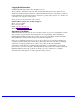
Flex CPU Piggyback Board Hardware Reference Table of Contents INTRODUCTION .......................................................................................................................................................1 BOARD CONFIGURATION .....................................................................................................................................3 Non-Turbo CPU Base Configuration ...............................................................................................
Flex CPU Piggyback Board Hardware Reference ii Table of Contents
Flex CPU Piggyback Board Hardware Reference INTRODUCTION The Flex CPU piggyback board (Part # 300-603605-10x) for the PMAC/PMAC2 and Turbo PMAC/PMAC2 families of boards provides new high-end capabilities for these controllers and uses newer components with longer product lifetimes.
Flex CPU Piggyback Board Hardware Reference 2 Introduction
Flex CPU Piggyback Board Hardware Reference BOARD CONFIGURATION Non-Turbo CPU Base Configuration When assembled for a non-Turbo CPU, the DSP IC in U1 of the Flex CPU board contains all of the memory required for operation. Therefore, there are no ICs installed in the locations for external RAM: U11, U12, U13, U14, U15, and U16. The CPU is available in several speed options: 40 MHz (Option 5AF), 80 MHz (Option 5CF), and 160 MHz (Option 5EF).
Flex CPU Piggyback Board Hardware Reference 4 Board Configuration
Flex CPU Piggyback Board Hardware Reference HARDWARE SETUP Flex CPU Board Jumper Configuration Watchdog Timer Jumper Jumper E1 on the Turbo CPU board must be OFF for the watchdog timer to operate. This is a very important safety feature, so it is vital that this jumper be OFF in normal operation. E1 should be put ON only to debug problems with the watchdog timer circuit.
Flex CPU Piggyback Board Hardware Reference 6 Hardware Setup
Flex CPU Piggyback Board Hardware Reference OPERATION OF THE FLEX CPU Operation as Non-Turbo CPU When used as a non-Turbo CPU, the Flex CPU board operates in a manner that is fundamentally compatible with older CPU designs. However, there are a few issues to note: • The Flex CPU requires the use of V1.17 or newer firmware. There are few differences between the previous V1.16H firmware and the V1.17 firmware other than the addition of internal support for the Flex CPU design.
Flex CPU Piggyback Board Hardware Reference I54 Baud Rate I54 Baud Rate 0 1 2 3 4 5 6 7 600 900 1200 1800 2400 3600 4800 7200 8 9 10 11 12 13 14 15 9600 14,400 19,200 28,800 38,400 57,600 76,800 115,200 Note that these values can be different from those used on PMAC2 boards with jumper-set CPU frequencies (see below).
Flex CPU Piggyback Board Hardware Reference For a PMAC2 board with a saved value of 0 for I46, the serial baud rate is determined by the combination of I54 and the CPU frequency on a PMAC2 board as shown in the following table. These settings maintain backward compatibility. I54 Baud Rate for 40 MHz CPU 0 600 1 900* (-0.05%) 2 1200 3 1800* (-0.1%) 4 2400 5 3600* (-0.19%) 6 4800 7 7200* (-0.38%) 8 9600 9 14,400*(-0.75%) 10 19,200 11 28,800*(-1.5%) 12 38,400 13 57,600*(-3.
Flex CPU Piggyback Board Hardware Reference 10 Operation of the Flex CPU
Flex CPU Piggyback Board Hardware Reference FLEX CPU BOARD JUMPER DESCRIPTIONS E1: Watchdog Disable Jumper E Point and Physical Layout E1 Description Jump pin 1 to 2 to disable Watchdog timer (for test purposes only). Remove jumper to enable Watchdog timer. Default No jumper installed E2: Dual-Ported RAM Port Select E Point and Physical Layout E2 Description Jump pin 1 to 2 to access DPRAM from baseboard.
Flex CPU Piggyback Board Hardware Reference E10A, B, C: Flash Memory Bank Select E Point and Physical Layout E10A Description Default Remove all 3 jumpers to select flash memory bank with factory-installed firmware.
Flex CPU Piggyback Board Hardware Reference CONNECTOR SUMMARY J2: JEXP Expansion Port (50-pin IDC header for Delta Tau accessory boards) J5: JTAG/OnCE Port (for factory use only) J6: JSIO Port (for factory use only) J7: JISP Port (for factory use only) J8: Auxiliary Serial Port (10-pin IDC header)* P1: Stack Connector (Internal connections to main PMAC board) P3: Stack Connector (Internal connections to main PMAC board) *Pinout shown in next section Connector Summary 13
Flex CPU Piggyback Board Hardware Reference 14 Connector Summary
Flex CPU Piggyback Board Hardware Reference CONNECTOR PINOUTS J8 JRS232 (10-Pin Connector) Front View Pin # Symbol Function Description Notes 1 N.C. No Connect 2 DTR Bidirect Data Terminal Ready Tied to DSR 3 TXD/ Input Receive Data Host transmit data 4 CTS Input Clear to Send Host ready bit 5 RXD/ Output Send Data Host receive data 6 RTS Output Request to Send PMAC ready bit 7 DSR Bidirect Data Set Ready Tied to DTR 8 N.C.
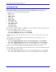
C24 (jisp) J7 +3P3V .1UF 1 2 3 4 TMS GND TCK RDBA05 RDFLASHCSBSCAN- BA06 BA07 BA08 BA09 PRAMCS- 6 7 8 C25 BA10 BA11 .1UF BA12 BA13 +3P3V WR- HSIP8NO5 C21 .01UF BA14 BA15 GND OE1 A0 A1 GND A2 A3 VCC A4 A5 GND A6 A7 A8 A9 GND A10 A11 VCC A12 A13 GND A14 A15 OE2 BA12 BA13 10 .
8 7 6 5 THIS DOCUMENT IS THE CONFIDENTIAL PROPERTY OF DELTA TAU DATA SYSTEMS INC. AND IS LOANED SUBJECT TO RETURN UPON DEMAND. TITLE TO THIS DOCUMENT IS NEVER SOLD OR TRANSFERRED FOR ANY REASON. THIS DOCUMENT IS TO BE USED ONLY PURSUANT TO WRITTEN LICENSE OR WRITTEN INSTRUCTIONS OF DELTA TAU DATA SYSTEMS INC. ALL RIGHTS TO DESIGNS AND INVENTIONS ARE RESERVED BY DELTA TAU DATA SYSTEMS INC. POSSESSION OF THIS DOCUMENT INDICATES ACCEPTANCE OF THE ABOVE AGREEMENT.