
Reference Manual


Flex CPU Piggyback Board Hardware Reference
Flex CPU Board Jumper Descriptions 11
FLEX CPU BOARD JUMPER DESCRIPTIONS
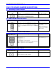
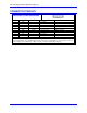
E1: Watchdog Disable Jumper
E Point and
Physical Layout
Description Default
E1
Jump pin 1 to 2 to disable Watchdog timer (for test
purposes only).
Remove jumper to enable Watchdog timer.
No jumper installed
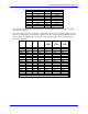
E2: Dual-Ported RAM Port Select
E Point and
Physical Layout
Description Default
E2
Jump pin 1 to 2 to access DPRAM from baseboard.
Jump pin 2 to 3 to access DPRAM through JEXP
expansion port (PMAC(1)-PC with Option 2 DPRAM
board).
Pins 2 and 3 jumpered
(with PMAC(1)-PC base
board only)
Pins 1 and 2 jumpered
(when used on all other
base boards)
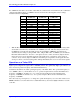
E4 – E6: Power-Up/Reset Load Source
E Point and
Physical Layout
Description Default
E6
E4
Remove jumper E4;
jump E5 pin 1 to 2;
jump E6 pin 2 to 3;
to read flash IC on power-up/reset
Other combinations are for factory use only; the board
will not operate in any other configuration.
No E4 jumper installed;
E5 and E6 jump pin 1 to 2
E7: Firmware Reload Enable
E Point and
Physical Layout
Description Default
E7
Jump pin 1 to 2 to reload firmware through serial or
bus port.
Remove jumper for normal operation.
No jumper installed