^1 HARDWARE REFERENCE MANUAL PMAC2A-PC/104 Axis Expansion Accessory-1P ^3 PMAC2A-PC/104 ACC-1P Hardware Reference ^4 4xx-603671-xHxx ^5 December 6, 2010 Single Source Machine Control Power // Flexibility // Ease of Use 21314 Lassen Street Chatsworth, CA 91311 // Tel. (818) 998-2095 Fax. (818) 998-7807 // www.deltatau.
Copyright Information © 2009 Delta Tau Data Systems, Inc. All rights reserved. This document is furnished for the customers of Delta Tau Data Systems, Inc. Other uses are unauthorized without written permission of Delta Tau Data Systems, Inc. Information contained in this manual may be updated from time-to-time due to product improvements, etc., and may not conform in every respect to former issues. To report errors or inconsistencies, call or email: Delta Tau Data Systems, Inc.
REVISION HISTORY REV. 1 2 3 DESCRIPTION ADDED ENCODER JUMPERS E20-E23 ADDED SOFTWARE SETUP INFO, P. 23 CORR. I-VARIABLES FOR USE WITH TURBO CPU DATE CHG APPVD 04/10/07 CP S. MILICI 10/15/09 10/01/10 CP SS S. MILICI S.
Hardware Reference Manual Table of Contents INTRODUCTION .......................................................................................................................................................4 Acc-1P: Axis Expansion Piggyback Board...........................................................................................................4 Acc-1P Option 1: I/O Ports ...............................................................................................................................
Hardware Reference Manual JOPTO port first ACC-1P, Jumper E6 on Position 1-2......................................................................................30 JTHW port first ACC-1P, Jumper E6 on Position 1-2........................................................................................31 JOPTO port second ACC-1P, Jumper E6 on Position 2-3 .................................................................................31 JTHW port second ACC-1P, Jumper E6 on Position 2-3 ....................
Hardware Reference Manual Table of Contents iii
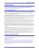
Hardware Reference Manual INTRODUCTION The PMAC2A PC/104 motion controller is a compact, cost-effective version of Delta Tau’s PMAC2 family of controllers. The PMAC2A PC/104 can be composed of three boards in a stack configuration. The baseboard provides four channels of either DAC ±10V or pulse and direction command outputs. The optional axis expansion board provides a set of four additional servo channels and I/O ports.
Hardware Reference Manual Introduction 5
Hardware Reference Manual HARDWARE SETUP On the Acc-1P, there are a number of jumpers called E-points or W-points that customize the hardware features of the CPU for a given application and must be setup appropriately. The following is an overview grouped in appropriate categories. For an itemized description of the jumper setup configuration, refer to the E-Point Descriptions section.
Hardware Reference Manual Differential Encoders Differential encoder signals (pin 2 to 3) can enhance noise immunity by providing common-mode noise rejection. Modern design standards virtually mandate their use for industrial systems, especially in the presence of PWM power amplifiers, which generate a great deal of electromagnetic interference. Connect pin 1 to 2 to tie differential line to +2.5V • Tie to +2.5V when no connection • Tie to +2.
Hardware Reference Manual Encoder 4 Handwheel Encoder RP37 RP55 6-pin 6-pin Handwheel Encoder Termination Resistors The PMAC provides a socket for termination resistors on the handwheel encoder differential input pairs coming into the board. As shipped, there is no resistor pack in the RP56 socket. If these signals are brought long distances into the PMAC board and ringing at signal transitions is a problem, a SIP resistor pack may be mounted on the RP56 socket to reduce or eliminate the ringing.
Hardware Reference Manual MACHINE CONNECTIONS Typically, the user connections are actually made to terminal blocks that are attached to the JMACH connectors by a flat cable.
Hardware Reference Manual Flags Power Supply Each channel of PMAC has five dedicated digital inputs on the machine connector: PLIMn, MLIMn (overtravel limits), HOMEn (home flag), FAULTn (amplifier fault), and USERn. A power supply from 5 to 24V must be used to power the circuits related to these inputs. This power supply can be the same used to power PMAC and can be connected from the TB1 terminal block or the JMACH1 connector.
Hardware Reference Manual DAC Output Signals If PMAC is not performing the commutation for the motor, only one analog output channel is required to command the motor. This output channel can be either single-ended or differential, depending on what the amplifier is expecting. For a single-ended command using PMAC channel 1, connect DAC1+ (pin 29) to the command input on the amplifier. Connect the amplifier’s command signal return line to PMAC’s GND line (pin 48).
Hardware Reference Manual Amplifier Fault Signal (FAULT-) This input can take a signal from the amplifier so PMAC knows when the amplifier is having problems, and can shut down action. The polarity is programmable with I-variable Ix25 (I125 for motor 1) and the return signal is ground (GND). FAULT1- is pin 35. With the default setup, this signal must actively be pulled low for a fault condition. In this setup, if nothing is wired into this input, PMAC will consider the motor not to be in a fault condition.
Hardware Reference Manual Further software settings are required to configure this port. See the Software Setup section for details. Thumbwheel Multiplexer Port (JTHW Port) The Thumbwheel Multiplexer Port, or Multiplexer Port, on the JTHW connector has sixteen lines. These lines can be used to multiplex large numbers of inputs and outputs on the port, and Delta Tau provides accessory boards and software structures (special M-variable definitions) to capitalize on this feature.
Hardware Reference Manual When used as non-multiplexed I/O, jumpers E7 and E8 select the I/O lines direction of the JTHW connector. This allows configuring this port as all inputs, all outputs or half inputs and half outputs. If E7 is removed or E8 is installed then the multiplexing feature if the JTHW port cannot be used. Handwheel Port (JHW / PD Port) This port provides an extra encoder input or a set of pulse and direction outputs.
Hardware Reference Manual Machine Connections Example: Using Analog ±10V Amplifier Machine Connections 15
Hardware Reference Manual Machine Connections Example: Using Pulse and Direction Drivers 16 Machine Connections
Hardware Reference Manual Machine Connections 17
Hardware Reference Manual SOFTWARE SETUP (non-Turbo PMAC2A-PC104) Note: The PMAC2A PC/104 requires the use of V1.17 or newer firmware. There are few differences between the previous V1.16H firmware and the V1.17 firmware other than the addition of internal support for the Flex CPU design. Communications Delta Tau provides software tools that allow communicating with of the PMAC2A PC/104 board by either its standard RS-232 port or the optional USB or Ethernet ports.
Hardware Reference Manual General-Purpose Digital Inputs and Outputs If one Acc-1P is present on the PMAC2A PC/104 stack configuration then its jumpers E5 and E6 should be set at the default position 1-2. In this case, the lines on its J7 general-purpose I/O connector will be mapped into PMAC’s address space in register Y:$C080. Jumpers E5 and E6 should be configured on position 2-3 only when two Acc-1Ps are used. In this case, the I/O lines can be accessed at address Y:$C0C0.
Hardware Reference Manual M2->Y:$C0C0,2 M3->Y:$C0C0,3 M4->Y:$C0C0,4 M5->Y:$C0C0,5 M6->Y:$C0C0,6 M7->Y:$C0C0,7 M8->Y:$C0C0,8 M9->Y:$C0C0,9 M10->Y:$C0C0,10 M11->Y:$C0C0,11 M12->Y:$C0C0,12 M13->Y:$C0C0,13 M14->Y:$C0C0,14 M15->Y:$C0C0,15 M32->X:$C0C0,0,8 M34->X:$C0C0,8,8 M40->X:$C0C4,0,24 M42->Y:$C0C4,0,24 ; ; ; ; ; ; ; ; ; ; ; ; ; ; ; ; ; ; Digital Output M02 Digital Output M03 Digital Output M04 Digital Output M05 Digital Output M06 Digital Output M07 Digital Input MI0 Digital Input MI1 Digital Input MI2 Di
Hardware Reference Manual Thumbwheel Port Digital Inputs and Outputs The inputs and outputs on the thumbwheel multiplexer port of either the Acc-1P or the Acc-2P boards may be used as discrete, non-multiplexed I/O. In this case, these I/O lines can be accessed through Mvariables that are defined according to the setup of the address selection jumpers.
Hardware Reference Manual Analog Inputs Setup The optional analog-to-digital converter inputs are ordered either through Option-12 on the baseboard or Option-2 on the axes expansion board. Each option provides two 12-bit analog inputs with a ±10Vdc range. The M-variables associated with these inputs provided a range of values between +2048 and – 2048 for the respective ±10Vdc input range. The following is the software procedure to setup and read these ports.
Hardware Reference Manual SOFTWARE SETUP (Turbo PMAC2A-PC104 and Clipper) Filtered DAC Outputs Configuration Although the Clipper Board uses standard Turbo PMAC2 firmware certain I-variables must be set properly to use the digital-to-analog (filtered DAC) outputs. For the first ACC-1P board, the E5 jumper should be set 1-2 to enable the four channels as motors 5-8 at base address $78100.
Hardware Reference Manual I8008=$78140;ECT Entry I8009=$78148;ECT Entry I8010=$78150;ECT Entry I8011=$78158;ECT Entry I8012=$0;ECT Entry 12 motor motor motor motor #9 #10 #11 #12 The following run once startup PLC will assign the correct clock values and other hardware settings for the third servo gate to properly set-up the filtered PWM DAC outputs: OPEN PLC 25 CLEAR M7200 = 1001 M7201 = 5 M7202 = 3 M7203 = 1746 M7204 = 15 M7205 = $7FFFC0 M7206 = $FFFFFE DIS PLC 25 CLOSE Motor Setup for channels 9-12 T
Hardware Reference Manual I903 = $3509 I904 = $3509 The default values not retained on a “SAVE” command must be added to the “run once startup PLC” from the previous section that set up the main hardware clocks: OPEN PLC 25 CLEAR // Main HDW Clocks M7200 = 1001 M7201 = 5 M7202 = 3 M7203 = 1746 M7204 = 15 M7205 = $7FFFC0 M7206 = $FFFFFE // Motor #9 defaults M7210 = 3 M7211 = 0 M7212 = 1 M7213 = 0 M7216 = 0 DIS PLC 25 CLOSE Note: After loading this program, set I5=2 or 3 and ENABLE PLC 1.
Hardware Reference Manual M7226 = //Motor I1024 = I1025 = I1069 = I1002 = I1003 = I1004 = 0 specific I-variables (retained on a "SAVE" command) 1 $78148 1001 $7814A $350A $350A The default values not retained on a “SAVE” command must again be added to the “run once startup PLC” from the previous section: OPEN PLC 25 CLEAR // Main HDW Clocks M7200 = 1001 M7201 = 5 M7202 = 3 M7203 = 1746 M7204 = 15 M7205 = $7FFFC0 M7206 = $FFFFFE // Motor #9 defaults M7210 = 3 M7211 = 0 M7212 = 1 M7213 = 0 M7216 = 0 // Moto
Hardware Reference Manual M7230->X:$78155,0,4 M7231->X:$78155,13,1 M7232->X:$78155,4,4 M7233->X:$78155,8,4 M7236->X:$78155,20,4 ;I7mn0 ;I7mn1 ;I7mn2 ;I7mn3 ;I7mn6 // Default values (NOT retained on a "SAVE" command) M7230 = 3 M7231 = 0 M7232 = 1 M7233 = 0 M7236 = 0 //Motor specific I-variables (retained on a "SAVE" command) I1124 = 1 I1125 = $78150 I1169 = 1001 I1102 = $78152 I1103 = $350B I1104 = $350B The default values not retained on a “SAVE” command must again be added to the “run once startup PLC”
Hardware Reference Manual // FOURTH CHANNEL OF GATE #3 - MOTOR #12 M1201->X:$078159,0,24,S ; ENC12 24-bit counter position M1202->Y:$07815A,8,16,S ; OUT12A command value; DAC or PWM M1203->X:$07815B,0,24,S ; ENC12 captured position M1214->X:$07815D,14 ; AENA12 output status M1215->X:$078158,19 ; USER12 flag input status M1217->X:$078158,11 ; ENC12 capture flag M1218->X:$078158,8 ; ENC12 count error flag M1219->X:$078158,14 ; CHC12 input status M1220->X:$078158,16 ; HMFL12 flag input status M1221->X:$078158
Hardware Reference Manual M7223 = 0 M7226 = 0 // Motor #11 defaults M7230 = 3 M7231 = 0 M7232 = 1 M7233 = 0 M7236 = 0 // Motor #12 defaults M7240 = 3 M7241 = 0 M7242 = 1 M7243 = 0 M7246 = 0 DIS PLC 25 CLOSE Note: After loading this program, set I5=2 or 3 and ENABLE PLC 1. Using Flag I/O as General-Purpose I/O Either the user flags or other unassigned axes flag on the ACC-1P board can be used as general-purpose I/O for up to 20 inputs and 4 outputs at 5-24Vdc levels.
Hardware Reference Manual General-Purpose Digital Inputs and Outputs If one Acc-1P is present then its jumper E6 should be set at the default position 1-2. In this case, the lines on its J7 general-purpose I/O connector will be mapped into PMAC’s address space at base address Y:$78500. If a second Acc-1P is used then its E6 jumper should be configured 2-3 and its I/O lines can be accessed at base address Y:$78540.
Hardware Reference Manual JTHW port first ACC-1P, Jumper E6 on Position 1-2 M4080->Y:$78502,8,1 ; SEL0 Output M4081->Y:$78502,9,1 ; SEL1 Output M4082->Y:$78502,10,1 ; SEL2 Output M4083->Y:$78502,11,1 ; SEL3 Output M4084->Y:$78502,12,1 ; SEL4 Output M4085->Y:$78502,13,1 ; SEL5 Output M4086->Y:$78502,14,1 ; SEL6 Output M4087->Y:$78502,15,1 ; SEL7 Output M4088->Y:$78502,8,8,U ; SEL0-7 Outputs treated as a byte M4090->Y:$78502,0,1 ; M4091->Y:$78502,1,1 ; M4092->Y:$78502,2,1 ; M4093->Y:$78502,3,1 ; M4094->Y:$78
Hardware Reference Manual M4114->Y:$78540,14 M4115->Y:$78540,15 M4117->Y:$78540,8,8,u ; Digital Input MI6 ; Digital Input MI7 ; all inputs as an 8bit word M4118->X:$78540,0,8 M4119->X:$78540,8,8 M4120->X:$78544,0,24 M4121->Y:$78544,0,24 ; ; ; ; Direction Control Direction Control Inversion control J9 port data type bits 0-7 (1=output, bits 8-15 (1=output, (0 = 0V, 1 = 5V) control (1 = I/O) 0 = input) 0 = input) In order to properly setup the JOPTO digital I/O, an initialization PLC must be written sc
Hardware Reference Manual CLOSE Note: After loading this program, set I5=2 or 3 and ENABLE PLC 1. Analog Inputs Setup The optional analog-to-digital converter inputs are ordered either through Option-2 on the axes expansion board. Each option provides two 12-bit analog inputs with a ±10Vdc range. The M-variables associated with these inputs provided a range of values between +2048 and –2048 for the respective ±10Vdc input range.
Hardware Reference Manual 34 Software Setup
Hardware Reference Manual HARDWARE REFERENCE SUMMARY The following information is based on the Acc-1P board, part number 603671-100.
Hardware Reference Manual Board Layout 1 2 3 4 5 6 A 36 B C D E Feature Location Feature Location E0 E1 E2 E3 E4 E5 E6 E7 E16 D6 F1 C6 B2 B2 E4 E4 E5 E5 E5 D1 F6 A1 RP30 RP31 RP36 RP37 RP55 RP56 TB1 JMACH1 JMACH2 JHW / PD J7 J2 E2 E2 E3 E3 E4 E5 B6 F4 A4 A2 A3 E4 F Hardware Reference Summary
Hardware Reference Manual Connectors and Indicators J2 - Thumbwheel Multiplexer Port (JTHW Port) The Thumbwheel Multiplexer Port, or Multiplexer Port, on the JTHW connector has eight input lines and eight output lines. The output lines can be used to multiplex large numbers of inputs and outputs on the port, and Delta Tau provides accessory boards and software structures (special M-variable definitions) to capitalize on this feature.
Hardware Reference Manual 38 Hardware Reference Summary
Hardware Reference Manual E-POINT JUMPER DESCRIPTIONS E0: Reserved for Future Use E Point and Physical Layout Location Description Default E0 C6 For future use. No jumper E1 - E2: Machine Output Supply Voltage Configure E Point and Physical Layout Location Description E1 B2 Jump pin 1 to 2 to apply +V (+5V to 24V) to pin 10 of U7 (should be ULN2803A for sink output configuration) JOPTO Machine outputs M01-M08.
Hardware Reference Manual E5: Servo Gate Address Select E Point and Physical Layout Location Description E5 E5 Jump pin 1 to 2 to address Acc-1P channels at the regular addresses for channels 5 to 8. Jump pin 2 to 3 to address Acc-1P channels at the regular addresses for channels 5 to 8 plus $40. Default 1-2 Jumper installed E6: I/O Gate Address Select E Point and Physical Layout Location E6 E5 Description Default Jump pin 1 to 2 to address Acc-1P I/O ports at the regular addresses.
Hardware Reference Manual CONNECTOR PINOUTS TB1 (JPWR): Power Supply (4-Pin Terminal Block) Top View Pin# Symbol Function 1 2 GND +5V Common Input Description Notes Reference Voltage Positive Supply Voltage Supplies all PMAC digital circuits 3 +12V Input Positive Supply Voltage REF to digital GND 4 -12V Input Negative Supply Voltage REF to digital GND This terminal block can be used to provide the input for the power supply for the circuits on the PMAC board when it is not in a bus configuration
Hardware Reference Manual J2 (JTHW): Multiplexer Port Connector (26-Pin Connector) Pin# Symbol Front View Function Description Notes 1 GND Common PMAC Common 2 GND Common PMAC Common 3 DAT0 Input Data-0 Input Data input from multiplexed accessory 4 SEL0 Output Select-0 Output Multiplexer select output 5 DAT1 Input Data -1 Input Data input from multiplexed accessory 6 SEL1 Output Select -1 Output Multiplexer select output 7 DAT2 Input Data -2 Input Data input from multiplexed accessory 8 SEL2 Output S
Hardware Reference Manual J3 (JMACH1): Machine Port Connector (50-Pin Header) Top View Pin# Symbol Function 1 2 3 4 5 6 7 8 9 10 11 12 13 14 15 16 17 18 19 20 21 22 23 24 25 26 27 28 29 30 31 32 33 34 35 36 37 38 39 +5V +5V GND GND CHA5 CHA6 CHA5/ CHA6/ CHB5 CHB6 CHB5/ CHB6/ CHC5 CHC6 CHC5/ CHC6/ CHA7 CHA8 CHA7/ CHA8/ CHB7 CHB8 CHB7/ CHB8/ CHC7 CHC8 CHC7/ CHC8/ DAC5 DAC6 DAC5/ DAC6/ AENA5/ AENA6/ FAULT5/ FAULT6/ DAC7 DAC8 DAC7/ Output Output Common Common Input Input Input Input Input Input Input Inp
Hardware Reference Manual J3 JMACH1 (50-Pin-Header) (Continued) Top View Pin# Symbol Function Description Notes 40 DAC8/ Output Analog Out Negative 8 4,5 41 AENA7/ Output Amplifier-Enable 7 42 AENA8/ Output Amplifier -Enable 8 43 FAULT7/ Input Amplifier -Fault 7 6 44 FAULT8/ Input Amplifier -Fault 8 6 45 ADCIN_1 Input Analog Input 1 Option-2 required 46 ADCIN_2 Input Analog Input 2 Option-2 required 47 FLT_FLG_V Input Amplifier Fault pull-up V+ 48 GND Input Analog Common 49 A+15V Input DACs +15V Supp
Hardware Reference Manual J4 (JMACH2): Machine Port Connector (34-Pin Header) Pin# Symbol FLG_5_6_V FLG_7_8_V Function Front View Description Notes 1 Input Flags 5-6 Pull-Up 2 Input Flags 7-8 Pull-Up 3 GND Common Digital Common 4 GND Common Digital Common 5 HOME5 Input Home-Flag 5 10 6 HOME6 Input Home-Flag 6 10 7 PLIM5 Input Positive End Limit 5 8,9 8 PLIM6 Input Positive End Limit 6 8,9 9 MLIM5 Input Negative End Limit 5 8,9 10 MLIM6 Input Negative End Limit 6 8,9 11 USER5 Input User Flag 5 12 USER
Hardware Reference Manual J7 (JOPTO): I/O Port Connector (34-Pin Connector) Front View Pin# Symbol Function Description 1 2 3 4 5 6 7 8 9 10 11 12 13 14 15 16 17 MI8 GND MI7 GND MI6 GND MI5 GND MI4 GND MI3 GND MI2 GND MI1 GND MO8 Input Common Input Common Input Common Input Common Input Common Input Common Input Common Input Common Output Machine Input 8 PMAC Common Machine Input 7 PMAC Common Machine Input 6 PMAC Common Machine Input 5 PMAC Common Machine Input 4 PMAC Common Machine Input 3 PMAC
Hardware Reference Manual J8 (JHW) Handwheel Encoder Connector Pin# Symbol Function 1 2 GND HWA1+ / PUL1+ HWA1- / PUL1HWB1+ / DIR1+ HWB1- / DIR1HWA2+ / PUL2+ HWA2- / PUL2HWB2+ / DIR2+ HWB2- / DIR2+5V Common Input/Output Reference voltage HW1 Channel A or pulse output selected by jumpers E3 and E4 Input/Output HW 1 Channel A or pulse output selected by jumpers E3 and E4 Input/Output HW 1 Channel B or direction output selected by jumpers E3 and E4 Input/Output HW 1 Channel B or direction output s
Hardware Reference Manual 48 Connector Pinouts
Hardware Reference Manual SCHEMATICS Connector Pinouts 49
Hardware Reference Manual THIS DOCUMENT IS THE CONFIDENTIAL PROPERTY OF DELTA TAU DATA SYSTEMS INC. AND IS LOANED SUBJECT TO RETURN UPON DEMAND. TITLE TO THIS DOCUMENT IS NEVER SOLD OR TRANSFERRED FOR ANY REASON. THIS DOCUMENT IS TO BE USED ONLY PURSUANT TO WRITTEN LICENSE OR WRITTEN INSTRUCTIONS OF DELTA TAU DATA SYSTEMS INC. ALL RIGHTS TO DESIGNS AND INVENTIONS ARE RESERVED BY DELTA TAU DATA SYSTEMS INC. POSSESSION OF THIS DOCUMENT INDICATES ACCEPTANCE OF THE ABOVE AGREEMENT.
1 3 5 7 9 11 13 15 17 19 21 23 25 27 29 31 33 35 37 39 BD01_A BD03_A BD05_A BD07_A BD09_A BD11_A BD13_A BD15_A BD17_A BD19_A BD21_A BD23_A BA01_A BA03_A BA05_A BA07_A BA09_A BA11_A BA13_A 2 4 6 8 10 12 14 16 18 20 22 24 26 28 30 32 34 36 38 40 BD01_A BD03_A BD05_A BD07_A BD09_A BD11_A BD13_A BD15_A BA01_A BA03_A BA05_A BA07_A BA09_A BA11_A BA13_A HEADER 20X2(FEM) CLS120LDDV C100 1 RP13A 2 4 R10 47PF 5 U15B 47KSIP8I (SO14) 4 47KSIP8I 200.