
User's Manual

Turbo PMAC User Manual
106 Setting Up Turbo PMAC-Based Commutation and/or Current Loop
Example
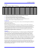
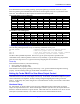
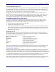
The table of results for a sample run of this test is:
Step M102 (A) M104 (B) M107 (C) Cycle Position Physical Position M101 (counts) M105 (A) M106 (B)
1 +500 0 -500
0
o
e
4:00 8820 < 0
≈ 0
2 +500 -500 0
+60
o
e
3:00 9184 < 0 > 0
3 0 -500 +500
+120
o
e
2:00 9501
≈ 0
> 0
4 -500 0 +500
+
180
o
e
1:00 9845 > 0
≈ 0
5 -500 +500 0
-120
o
e
12:00 10218 > 0 < 0
6 0 +500 -500
-60
o
e
11:00 10532
≈ 0
< 0
1 +500 0 -500
0
o
e
10:00 10869 < 0
≈ 0
From this test, we can conclude:
• PWM operation is fundamentally working (we got 6 approximately equal steps)
• We have a 4-pole motor because we moved 1/2 revolution
• Current ADC inputs are working: we got proportionate responses
• Sign of current is opposite to sign of voltage, so Ixx72 should be 683.
• We move 2049 counts in one cycle, so 4096 counts per revolution should be correct
• Encoder counter increased, so commutation polarity is correct
Cleaning Up
When done with this section of the testing, write zero values into the command registers and disable the
amplifier with the command:
M102=0 M104=0 M107=0 M114=0
With zero commands into all of the phases of the drive, with the drive either enabled or disabled, the
ADC registers should read nearly zero. Turbo PMAC can compensate for non-zero values with the offset
parameters Ixx79 (A-phase offset) and Ixx29 (B-phase offset). These offset parameters should hold
values of the opposite sign of the phases’ ADC values when there are zero PWM commands. Ixx29 and
Ixx79 magnitudes assume 16-bit values; since we are using 16-bit M-variables to look at the ADC
registers, regardless of the true resolution of the ADCs, we can just read the M-variable values at zero
command and use the opposite values for Ixx79 and Ixx29.
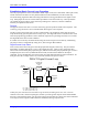
Debugging
With zero commands on the three output registers, you can observe any of the six PWM output signals
with an oscilloscope. All six should have 50% duty cycle (minus the deadtime set by I7m04) at the
frequency set by I7m00. All three top-PWM signals should be in phase with each other. All three
bottom-PWM signals should be in phase with each other, and one-half cycle out of phase with the top
signals. Observing a top and bottom pair, observe the deadtime between the top and bottom on times.
With a positive command into the A-phase, a negative command into the B-phase, and a zero command on
the C-phase, these waveforms should change. On the oscilloscope, observe PWMATOP1 on-time increase,
and PWMABOT1 on-time decrease, while maintaining the deadtime. Similarly, PWMBTOP1 on-time
should decrease, and PWMBBOT1 on-time should increase, maintaining the deadtime between them.
If the analog voltages representing the current measurements are available, these can be probed for
diagnostic purposes. Many direct PWM drives provide analog current measurement outputs and the A/D
conversion is done on an interface board. The probing is easy for these drives. If the A/D conversion is
done inside the drive, access to test points to probe these voltage levels. Consult the drive manual for
location and scaling of these signals.