
User's Manual


Turbo PMAC User Manual
352 Synchronizing Turbo PMAC to External Events
Triggered Time Base
The time-base techniques discussed so far keep the slave coordinate system locked perfectly to the
master, but they do not provide a way of synchronizing to a particular point on the master. Thus, the
slave cycle can be out of phase with the master cycle, and some special technique, usually involving
position capture from a registration mark, must be used to bring the cycles in phase with each other.
Many time-base applications do not require the master and slave cycles to be in phase with each other (for
instance, cutting blank sheets of paper to length rather than printed pages), and others have to be
continually re-registered due to stretching, slippage, or uneven spacing. These types of applications can
use the standard time base function.
However, applications that do need to be in phase with the master, and in which a registration procedure
to do this is difficult or impossible, can use the triggered time base feature of the conversion table. This
technique permits perfect synchronization to the position of the master that is captured by a trigger, by
freezing the time base until the trigger is received, then starting the time base referenced to the position
that was captured by that trigger.
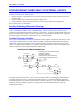
The triggered time-base entry in the conversion table is similar to the standard time-base entry. It is a
two-line entry, with the first line specifying the process and the source address for the master encoder
data, and the second line specifying the time-base scale factor. There are two important differences
between the triggered time-base entry and the standard time base entry. First, the value specifying the
process is different, and it is changed during the process of triggering ($90, $A0, and $B0, versus the $40
for standard time-base). Second, the source address is that of the actual master encoder counter registers,
not the processed encoder data in the conversion table. The scale factor is the same as for the standard
time-base. The rules for this entry are discussed in detail in the instructions for the conversion table.
Instructions for the Triggered Time-Base
Using the triggered time-base feature involves proper setup of I-variable values, M-variable definitions,
and conversion table entries (these can be done ahead of time), writing motion programs, and writing PLC
programs. Each of these is covered in turn below.
Step 1: Signal Decode Setup
The signal decoding of the master signal is the same as for standard time-base: the quadrature or pulse
and direction signal must be decoded so that the counter counts up. This is set with I7mn0.
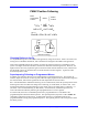
Step 2: Interpolation and Time-Base Setup
The triggered time-base conversion in the encoder conversion table handles both the 1/T count
interpolation and the time-base calculation from the interpolated value. In this method, the 1/T
interpolation produces three additional fractional count bits (for a total of eight), making the resulting
numerical value for a given count eight times bigger than “normal” 1/T interpolation. In the initial setup,
a triggered time-base entry is created in the conversion table, usually in the running (not frozen or
waiting-for-trigger) state. The time base scale factor is also entered here; it is calculated in the same
manner as for the standard time base, except that it is only 1/8 as big for the same real-time input
frequency.
Step 3: Writing the Motion Program
In writing the motion program that is to use triggered time base, all of the axes must be brought to a stop
at the point where they will wait for the trigger. If this is not at the beginning of the motion, the section
should be preceded immediately by a DWELL command.
At the start of the calculations for the moves that are to be started on the trigger, the time base should be
frozen to prevent the move from starting. This is best done by using an M-variable that has been assigned
to the process bits for the triggered time base entry in the conversion table. If the previous moves were
done working from a different time-base source, the time-base address for the coordinate system – Ix93 –
should be changed to the triggered time-base entry.