^1 HARDWARE REFERENCE MANUAL ^2 Turbo PMAC Clipper ^3Turbo PMAC Clipper ^4 4xx-603871-xAxx ^5April 15, 2014 DELTA TAU Data Systems, Inc. NEW IDEAS IN MOTION … Single Source Machine Control ……………………………………………..…...………………. Power // Flexibility // Ease of Use 21314 Lassen St. Chatsworth, CA 91311 // Tel. (818) 998-2095 Fax. (818) 998-7807 // www.deltatau.
Turbo PMAC Clipper Copyright Information © 2014 Delta Tau Data Systems, Inc. All rights reserved. This document is furnished for the customers of Delta Tau Data Systems, Inc. Other uses are unauthorized without written permission of Delta Tau Data Systems, Inc. Information contained in this manual may be updated from time-to-time due to product improvements, etc., and may not conform in every respect to former issues. To report errors or inconsistencies, call or email: Delta Tau Data Systems, Inc.
Turbo PMAC Clipper Safety Instructions Qualified personnel must transport, assemble, install, and maintain this equipment. Properly qualified personnel are persons who are familiar with the transport, assembly, installation, and operation of equipment. The qualified personnel must know and observe the following standards and regulations: IEC364resp.
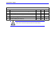
Turbo PMAC Clipper REVISION HISTORY REV. DESCRIPTION DATE CHG APPVD 9 Changed name of manual to Turbo PMAC Clipper 11/03/09 CP DD 10 Adjusted diagram on P.31 12/16/09 CP SM 11 Added pulse and direction setup, updated fifth motor setup 06/10/10 RN SM 12 Updated power supply information 03/17/12 GS SM 13 General formatting and corrections 04/15/14 MC RN Older revision correction notes have been removed for clarity.
Turbo PMAC Clipper Table of Contents INTRODUCTION ................................................................................................................................. 9 Documentation ........................................................................................................................................ 9 Downloadable Turbo PMAC Script ....................................................................................................... 10 SPECIFICATIONS .......................
Turbo PMAC Clipper J12: Ethernet Communications Port ....................................................................................................... 43 J13: USB Communications Port ............................................................................................................ 43 JP11: OPT-11 Shunt .............................................................................................................................. 43 LED Indicators ..............................................
Turbo PMAC Clipper E5: Reserved for factory use only ......................................................................................................... 74 E6: ADC Inputs Enable ........................................................................................................................ 75 E7 – E8: USB/Ethernet Reset Jumpers .................................................................................................. 75 E10 – E12: Flash IC Jumpers .....................................
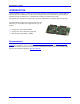
Turbo PMAC Clipper INTRODUCTION The Turbo PMAC Clipper is a multi-axis stand-alone controller. It has the full power of Turbo PMAC2 CPU and provides a minimum of 4 axes of servo or stepper control. It comes with 32 general-purpose digital I/O points, handwheel port, USB, Ethernet and RS-232 communications links. The optional axis expansion board provides a set of four additional servo channels and extra I/O ports.
Turbo PMAC Clipper Downloadable Turbo PMAC Script Caution Some code examples require the user to input specific information pertaining to their system hardware. When user information is required, a commentary ending with –User Input is inserted. This manual contains downloadable code samples in Turbo PMAC script. These examples can be copied and pasted into the editor area in the Pewin32pro2.
Turbo PMAC Clipper SPECIFICATIONS Part Number Connections and Software Setup 11
Turbo PMAC Clipper Options CPU Options C0: 80MHz Turbo PMAC2 CPU (standard) 8Kx24 internal memory, 256Kx24 SRAM , 1MB flash memory C3: 80MHz Turbo PMAC2 CPU 8Kx24 internal memory, 1Mx24 SRAM, 4M flash memory F3: 240MHz Turbo PMAC2 CPU 192Kx24 internal memory, 1Mx24 SRAM, 4M flash memory Communication Options Opt.2 Dual Port RAM (required for NC software/applications) Opt.15F Modbus Communication for additional I/O’s. Opt.EX JEXPA & JEXPB stack long pins Opt.
Turbo PMAC Clipper Environmental Specifications Description Specification Operating Temperature 0°C to 45°C Storage Temperature -25°C to 70°C Humidity 10% to 95 % Notes Non-Condensing Electrical Specifications Digital Power Supply The +5V and ground reference lines from the power supply should be connected to TB1 terminal block of the Turbo PMAC Clipper board using 18 AWG stranded wire.
Turbo PMAC Clipper RECEIVING AND UNPACKING Delta Tau products are thoroughly tested at the factory and carefully packaged for shipment. When the Turbo PMAC Clipper is received, there are several things to be done immediately: Observe the condition of the shipping container and report any damage immediately to the commercial carrier that delivered the board. Remove the Turbo PMAC Clipper from the shipping container and remove all packing materials.
Turbo PMAC Clipper MOUNTING The location of the Turbo PMAC Clipper is important. Installation should be in an area that is protected from direct sunlight, corrosives, harmful gases or liquids, dust, metallic particles, and other contaminants. Exposure to these can reduce the operating life and degrade performance of the board.
Turbo PMAC Clipper Physical Specifications Board Dimensions and Layout Top View Rev106 Connections and Software Setup 16
Turbo PMAC Clipper Hardware Reference Manual CONNECTIONS AND SOFTWARE SETUP WARNING Installation of electrical equipment is subject to many regulations including national, state, local, and industry guidelines and rules. The following are general recommendations but it is important that the integration be carried out in accordance with all regulations pertaining to the installation.
Turbo PMAC Clipper Hardware Reference Manual J2: Serial Port This connector allows communicating with Turbo PMAC Clipper from a host computer through a RS232 port. Delta Tau provides the Accessory 3L cable that connects the PMAC to a DB-9 connector. This port can be used as a primary communication mean or employed as a secondary port that allows simultaneous communication.
Turbo PMAC Clipper Hardware Reference Manual J3: Machine Connector (JMACH1 Port) The primary machine interface connector is JMACH1, labeled J3 on the Turbo PMAC Clipper. It contains the pins for four channels of machine I/O: analog outputs, incremental encoder inputs, amplifier fault and enable signals and power-supply connections.
Turbo PMAC Clipper Hardware Reference Manual 28 CHC4/ Input 29 DAC1 Output Analog Output Positive 1 4 30 DAC2 Output Analog Output Positive 2 4 31 DAC1/ Output Analog Output Negative 1 4,5 32 DAC2/ Output Analog Output Negative 2 4,5 33 AENA1/ Output Amplifier-Enable 1 34 AENA2/ Output Amplifier -Enable 2 35 FAULT1/ Input Amplifier -Fault 1 6 36 FAULT2/ Input Amplifier -Fault 2 6 37 DAC3 Output Analog Output Positive 3 4 38 DAC4 Output Analog Output Positive
Turbo PMAC Clipper Hardware Reference Manual 50-pin female flat cable connector T&B Ansley P/N 609-5041 Standard flat cable stranded 50-wire T&B Ansley P/N 171-50 Phoenix varioface module type FLKM 50 (male pins) P/N 22 81 08 9 Use an encoder cable with high quality shield. Note The standard encoder inputs on the Turbo PMAC Clipper are designed for differential quadrature type signals. Quadrature encoders provide two digital signals to determine the position of the motor.
Turbo PMAC Clipper Hardware Reference Manual Differential Quadrature Encoder Wiring for Channel #1 J3(JMACH1) 25 24 23 22 21 20 19 18 17 GND 1 2 A+ 3 4 A- 5 6 B+ 7 8 B- 9 10 C+ 11 12 13 14 15 16 C- +5V Note Encoder shield For single-ended encoders, leave the complementary signal pins floating – do not ground them. Alternately, some open collector single ended encoders may require tying the negative pins to ground in series with a 1-2 KOhm resistors.
Turbo PMAC Clipper Hardware Reference Manual ACC-51S channels 1 – 4 become PMAC channels 1 – 4 if ACC51S jumper E1 connects pins 2 and 3. ACC-51S channels 1 – 4 become PMAC channels 5 – 8 if ACC 51S jumper E1 connects pins 1 and 2. Note The Sinusoidal position feedback is set up through the Encoder Conversion Table (ECT) as a high resolution interpolation entry. Encoder Conversion Table Setup Example, Channel 1 1. 2. 3. 4. Channel # 1 2 3 4 Conversion Type: High res.
Turbo PMAC Clipper Hardware Reference Manual The equivalent Turbo PMAC script code for 8-channel entries // Channel 1 I8000=$FF8000 I8001=$078800 I8002=$000000 // Channel 2 I8003=$FF8008 I8004=$078802 I8005=$000000 // Channel 3 I8006=$FF8010 I8007=$078804 I8008=$000000 // Channel 4 I8009=$FF8018 I8010=$078806 I8011=$000000 // Channel 5 I8012=$FF8100 I8013=$078808 I8014=$000000 // Channel 6 I8015=$FF8108 I8016=$07880A I8017=$000000 // Channel 7 I8018=$FF8110 I8019=$07880C I8020=$000000 // Channel 8 I8021=$FF
Turbo PMAC Clipper Hardware Reference Manual Wiring the DAC Output Example for Clipper Channel #1 Single Ended DAC Output 49 47 45 43 41 39 37 35 33 33 34 35 34 36 37 36 38 39 38 40 41 40 42 43 42 44 45 44 46 47 46 48 49 48 31 29 27 25 25 26 27 26 28 29 28 30 31 30 32 32 Analog DAC1+ Device 50 50 COM Differential DAC Output COM DAC1DAC1+ Analog Device 23 23 J3 (JMACH1) Note J3 (JMACH1) The analog outputs are intended to drive high-impedance inputs with no
Turbo PMAC Clipper Hardware Reference Manual Amplifier Enable Signal (AENAn/DIRn) Most amplifiers have an enable/disable input that permits complete shutdown of the amplifier regardless of the voltage of the command signal. PMAC’s AENA line is meant for this purpose. AENA1- is pin 33. This signal is an open-collector output and an external 3.3 k pull-up resistor can be used if necessary.
Turbo PMAC Clipper Hardware Reference Manual Amplifier Fault Signal (FAULT-) This input can take a signal from the amplifier so PMAC knows when the amplifier is having problems, and can shut down action. The polarity is programmable with I-variable Ixx24 (I124 for motor 1) and the return signal is ground (GND). FAULT1- is pin 35. With the default setup, this signal must actively be pulled low for a fault condition.
Turbo PMAC Clipper Hardware Reference Manual Optional Analog Inputs The optional analog-to-digital converter inputs are ordered either through Option-12 on the Turbo PMAC Clipper or Option-2 on the axis expansion board. Each option provides two 12-bit analog inputs with a ±10Vdc range, and one 12-bit filtered PWM DAC output.
Turbo PMAC Clipper Hardware Reference Manual J4: Machine Connector (JMACH2 Port) This machine interface connector is labeled JMACH2 or J4 on the Turbo PMAC Clipper. It contains the pins for four channels of machine I/O: end-of-travel input flags, home flag and pulse-and-direction output signals. In addition, the B_WDO output allows monitoring the state of the Watchdog safety feature.
Turbo PMAC Clipper Hardware Reference Manual 27 PUL_3 Output Pulse Output 3 28 PUL_4 Output Pulse Output 4 29 DIR_3 Output Direction Output 3 30 DIR_4 Output Direction Output 4 31 EQU3 Output Encoder Comp-Equal 3 32 EQU4 Output Encoder Comp-Equal 4 33 B_WDO Output Watchdog Out Indicator/driver 34 INIT- Input PMAC Reset Low is Reset. See note 11 Note Note 8: Pins marked PLIMn should be connected to switches at the positive end of travel.
Turbo PMAC Clipper Hardware Reference Manual Example for Normally Close Switch J4(JMACH2) 34 33 32 31 30 29 28 27 USER 4 26 25 USER 3 NC NEG. LIMIT 4 24 23 NC NEG. LIMIT 3 NC POS. LIMIT 4 22 21 NC POS. LIMIT 3 HOME 4 20 19 HOME 3 18 17 16 15 14 13 3 5 HOME 1 4 NC POS. LIMIT 1 6 + COM FLAG RETURN 1-2 1 2 FLAG RETURN 3-4 8 HOME 2 NC NEG. LIMIT 1 7 10 NC POS. LIMIT 2 USER 1 9 12 NC NEG.
Turbo PMAC Clipper Hardware Reference Manual Example for 15-24V Proximity Switch J4(JMACH2) 34 33 32 31 30 29 28 27 USER 4 26 25 USER 3 NC NEG. LIMIT 4 24 23 NC NEG. LIMIT 3 NC POS. LIMIT 4 22 21 NC POS. LIMIT 3 HOME 4 20 19 HOME 3 18 17 16 15 14 13 3 5 HOME 1 4 NC POS. LIMIT 1 6 + COM FLAG RETURN 1-2 1 2 FLAG RETURN 3-4 8 HOME 2 NC NEG. LIMIT 1 7 10 NC POS. LIMIT 2 USER 1 9 12 NC NEG.
Turbo PMAC Clipper Hardware Reference Manual Note While normally closed-to-ground switches are required for the overtravel limits inputs, the home switches could be either normally close or normally open types. The polarity is determined by the home sequence setup, through the I-variables I7mn2. Limits and Flags [Axis 1- 4] Suggested M-Variables Either the user flags or other not assigned axes flag on the base board can be used as general-purpose I/O for up to 20 inputs and 4 outputs at 5-24Vdc levels.
Turbo PMAC Clipper Hardware Reference Manual Step and Direction PFM Output (To External Stepper Amplifier) The Turbo PMAC Clipper or the Acc-1P has the capability of generating step and direction (Pulse Frequency Modulation) output signals to external stepper amplifiers. The step and direction outputs can be connected in single-ended configuration for 5V (input signal) amplifiers.
Turbo PMAC Clipper Hardware Reference Manual Compare Equal Outputs The compare-equals (EQU) outputs have a dedicated use of providing a signal edge when an encoder position reaches a pre-loaded value. This is very useful for scanning and measurement applications. Instructions for use of these outputs are covered in detail in the Turbo PMAC User Manual.
Turbo PMAC Clipper Hardware Reference Manual J7: Machine Connector (JMACH3 Port) This machine interface connector is labeled JMACH3 or J7 on the Turbo PMAC Clipper. It contains the pins for four channels of U, V, and W flags normally used for hall device commutation.
Turbo PMAC Clipper Hardware Reference Manual J8: Thumbwheel Multiplexer Port (JTHW Port) Thumbwheel Multiplexer Port on the JTHW connector has 8 inputs and 8 outputs at TTL levels. The output lines can be used to multiplex large numbers of inputs and outputs on the port, and Delta Tau provides accessory boards and software structures (special M-variable definitions) to capitalize on this feature. In this form, some of the SELn outputs are used to select which of the multiplexed I/O are to be accessed.
Turbo PMAC Clipper Hardware Reference Manual Note The direction of the input and output lines on this connector are set by jumpers E14 and E15. If E14 is removed or E15 is installed then the multiplexing feature of the JTHW port cannot be used. 26-pin female flat cable connector T&B Ansley P/N 609-2641 Standard flat cable stranded 26-wire T&B Ansley P/N 171.
Turbo PMAC Clipper Hardware Reference Manual J9: General-Purpose Digital Inputs and Outputs (JOPT Port) This connector provides 16 general-purpose inputs or outputs at TTL levels. Each input and each output has its own corresponding ground pin in the opposite row. The direction of the input and output lines on this connector are set by jumpers E16 and E17. The 34-pin connector was designed for easy interface to OPTO-22 or equivalent optically isolated I/O modules.
Turbo PMAC Clipper Hardware Reference Manual 27 MO3 Output Machine Output 3 28 GND Common PMAC Common 29 MO2 Output Machine Output 2 30 GND Common PMAC Common 31 MO1 Output Machine Output 1 32 GND Common PMAC Common 33 +5 Output 34 GND Common Note 11, 13 11, 13 11, 13 +5 Power I/O PMAC Common Note 11: To configure MO1 - MO8 as inputs install jumper E16. To configure MO1 - MO8 as outputs remove jumper E16. Note 12: To configure MI1 - MI8 as inputs install jumper E17.
Turbo PMAC Clipper Hardware Reference Manual General Purpose I/Os (J6) Suggested M-Variables The lines on the JOPT general-purpose I/O connector will be mapped into PMAC's address space in register Y:$78400. Typically, these I/O lines are accessed individually with M-variables. Following is a suggested set of M-variable definitions to use these data lines.
Turbo PMAC Clipper Hardware Reference Manual J10: Handwheel and Pulse/Dir Connector (JHW/PD Port) JHW/PD port provides two Quadrature encoder inputs and PFM or PWM output pairs from the DSPGate2 supplemental channels 1* and 2*.
Turbo PMAC Clipper Hardware Reference Manual J12: Ethernet Communications Port This connector is used to establish communication over Ethernet between the PC and the Turbo PMAC Clipper. A crossover cable is required if you are going directly to the Clipper from the PC Ethernet card, and not through a hub. Delta Tau strongly recommends the use of RJ45 CAT5e or better shielded cable.
Turbo PMAC Clipper Hardware Reference Manual DRIVE - MOTOR SETUP The Turbo PMAC Clipper supports three types of outputs: Analog ±10V 12-bit Filtered PWM Analog ±10V 18-bit True DAC with Acc-8ES Pulse Frequency Modulation (PFM) The following chart summarizes the steps to implement for setting up a motor properly with the Turbo PMAC Clipper: Encoder / Motor wiring Factory Default Reset $$$***, Save, $$$ (recommended) Encoder Software Setup. Verify Feedback. (rotate shaft by hand) Output Type i.e.
Turbo PMAC Clipper Hardware Reference Manual Filtered PWM Output (Analog ±10V) In this mode, the ±10V analog output is obtained by passing the digital PWM signal through a 10 KHz low pass filter. This technique, although not as performing as a true digital to analog converter, is more than adequate for most servo applications. The duty cycle of the PWM signal controls the magnitude of the voltage output. This is handled internally by the PMAC, the user needs not to change any settings.
Turbo PMAC Clipper Hardware Reference Manual Clock Settings, Output Mode, Command Limit Most commonly used and suggested clock settings in this mode allowing a good compromise are a 29.4 KHz PWM Frequency, 9.8 KHz Phase, and 2.45 KHZ Servo. DT Calculator Link I7000 I7001 I7002 I7003 = = = = 1001 5 3 1746 ; ; ; ; PWM Frequency 29.4 KHz, PWM 1-4 Phase Clock 9.8 KHz, Servo IC 0 Servo Clock 2.
Turbo PMAC Clipper Hardware Reference Manual Flag Control, Ixx24 The following diagram showcases important bit settings pertaining to flags, and amplifier information: Amplifier Fault Use Bit Amplifier Enable Use Bit Flag Register Type = 0 Enable amp fault input = 1 Disable amp fault input = 0 Use amp enable output = 1 Don’t use amp enable Always =1 for Turbo PMAC Clipper (Turbo PMAC) 23 Bit #: 22 21 20 19 18 17 16 15 14 13 12 11 Amplifier Fault Polarity Bit Overtravel Limit Use Bit =
Turbo PMAC Clipper Hardware Reference Manual Satisfactory Open-Loop Test Result The open-loop test is usually performed on an unloaded motor. The open loop command output is adjustable, start off with a conservative 1 to 2 percent command output (i.e. #nO2) value and increment gradually until you see a satisfactory result.
Turbo PMAC Clipper Hardware Reference Manual If the motor/axis direction does not comply now with the machine design then negative jog commands can be issued for positive motion, and vice versa. Similarly, for motion programs, the motor can then assigned to a negative axis definition. Position-Loop PID Gains: Ixx30…Ixx39 The position-loop tuning is done as in any Turbo PMAC PID-Loop setup. The PMACTuningPro2 automatic or interactive utility can be used to fine-tune the PID-Loop.
Turbo PMAC Clipper Hardware Reference Manual True DAC Output (±10V) Clock Settings, Output Mode Default Clock settings are suitable for most applications. Output mode is set to DAC. The following is a 4-channel true DAC setting’s Turbo PMAC script code for a Turbo PMAC Clipper and Acc-8ES. I7000 I7001 I7002 = 6527 = 0 = 3 ; Servo IC 0 PWM Frequency 4.5 KHz, Max Phase Frequency 9 KHz ; Servo IC 0 Phase Clock 9 Khz ; Servo IC 0 Servo Clock 2.
Turbo PMAC Clipper Hardware Reference Manual Open Loop Test: Encoder/Decode The open-loop test is critical to verify the direction sense of the encoder counting versus the command output. A positive command should create a positive velocity and a position counting in the positive direction; a negative command should create a negative velocity and a position counting in the negative direction. The Open Loop test utility in the PMACTuningPro2 Software can be used to execute and open loop test.
Turbo PMAC Clipper Hardware Reference Manual Quadrature | Sinusoidal: Change I7mn0 to 3 from 7 (default) or vice-versa. Absolute Serial Encoders (EnDat, SSI, BiSS, Yaskawa, Panasonic, Tamagawa, Mitutoyo): The Turbo PMAC Clipper has no control on the direction sense of the serial data stream (packets). There are no software parameters that allow changing the direction sense of absolute serial encoders. Normally, it is set by jumpers or software at the encoder side.
Turbo PMAC Clipper Hardware Reference Manual At this point of the setup, the motor(s) is ready to accept Jog commands.
Turbo PMAC Clipper Hardware Reference Manual Pulse and Direction Output (PFM) The Pulse and direction (Pulse Frequency Modulation) output pins are located on the J4 (JMACH2) connector. The stepper drive specifications dictate the choice of the maximum PFM clock frequency, and pulse width. DT Calculator Forum Link Step 1: Choose Max PFM clock by changing the PFM clock divider. Click on calculate to see results. Step 2: Choose PFM Pulse width by changing I7m04. Click on calculate to see results.
Turbo PMAC Clipper Hardware Reference Manual PFM Setup Example // Encoder Conversion I8000=$C78000 I8001=$C78008 I8002=$C78010 I8003=$C78018 Table, for ; Entry 1 ; Entry 2 ; Entry 3 ; Entry 4 channels 1-4 incremental encoder, incremental encoder, incremental encoder, incremental encoder, no no no no extension extension extension extension // Channels 1-4 Output Mode Select, Encoder/Decode I7016,4,10 = 3 ; Servo IC 0, Channels 1-4 Output Mode Select to PFM I7010,4,10 = 8 ; Servo IC 0, Channels 1-4 Enco
Turbo PMAC Clipper Hardware Reference Manual M407->Y:$7801C,8,16,S ; Channel 4, Min=0, Max= Calculated I469 // Channels 5-8 Suggested M-Variables, PFM M507->Y:$78104,8,16,S ; Channel 5, Min=0, M607->Y:$7810C,8,16,S ; Channel 6, Min=0, M707->Y:$78114,8,16,S ; Channel 7, Min=0, M807->Y:$7811C,8,16,S ; Channel 8, Min=0, command output Max= Calculated Max= Calculated Max= Calculated Max= Calculated I569 I669 I769 I869 (First (First (First (First // Channels 9-12 Suggested M-Variables, PFM command output M90
Turbo PMAC Clipper Hardware Reference Manual I603=$3506 I604=$3506 I703=$3507 I704=$3507 I803=$3508 I804=$3508 ; Channel 6 position and velocity pointers ; Channel 7 position and velocity pointers ; Channel 8 position and velocity pointers I903=$3509 I904=$3509 I1003=$350A I1004=$350A I1103=$350B I1104=$350B I1203=$350C I1204=$350C ; ; ; ; Channel Channel Channel Channel (First Acc-1P) (First Acc-1P) (First Acc-1P) 9 position and velocity pointers 10 position and velocity pointers 11 position and velo
Turbo PMAC Clipper Hardware Reference Manual // Channels 9-12 PID Gains (with default clock settings): I930,4,100 = 11190 ; Motors 9-12 Proportional Gain I931,4,100 = 0 ; Motors 9-12 Derivative Gain I932,4,100 = 15038 ; Motors 9-12 Velocity FeedForward Gain I933,4,100 = 0 ; Motors 9-12 Integral Gain I934,4,100 = 0 ; Motors 9-12 Integral Mode I935,4,100 = 0 ; Motors 9-12 Acceleration FeedForward Gain (Second (Second (Second (Second (Second (Second Acc-1P) Acc-1P) Acc-1P) Acc-1P) Acc-1P) Acc-1P) At this p
Turbo PMAC Clipper Hardware Reference Manual Setup of a Fifth Motor Using Opt-12 on the Clipper Board The DSPGATE2A supplemental channels are set with I6800-6807. Set these to the same values as specified for the filtered PWM outputs (leave I6804-I6807 at default). Example Turbo PMAC script code for motor 5: I6800 I6801 I6802 I6803 I6816 I569 = = = = = = 1001 5 3 1746 0 1001 ; ; ; ; ; ; PWM frequency 29.4kHz, PWM 1-4 Phase Clock 9.8kHz Servo frequency 2.
Turbo PMAC Clipper Hardware Reference Manual The equivalent Turbo PMAC script code Settings: M32->X:$78400,0,8 M34->X:$78400,8,8 M40->X:$78404,0,24 M42->Y:$78404,0,24 ; ; ; ; //Power-up PLC: Open plc 1 clear M32 = $00 M34 = $FF M40 = $0 M42 = $FF0F Disable plc 1 Close I925=$78410 I1025=$78418 I902 I1002 I6810 I6816 I6820 I6826 = = = = = = $78414 $7841C 8 3 8 3 Direction Control Direction Control Inversion control J9 port data type ; ; ; ; ; ; ; ; ; ; ; ; ; bits 0-7 (1=output, 0 = input) bits 8-15 (1
Turbo PMAC Clipper Hardware Reference Manual LASER CONTROL OUTPUT Clipper’s Option 11 consists of a programmable lattice chip which can be programmed based upon customer’s requirements. The main objective for this option is to be used as a laser controller. Different programs can be loaded in this chip based upon customers’ requirements and each code will be designated an alpha-numeric suffix after options number if the code is developed by Delta Tau and can be ordered at a later time with the same suffix.
Turbo PMAC Clipper Hardware Reference Manual dependent on the laser and differs for different manufacturers. For example the laser shown in the above graph, requires a 5kHz signal with 0.5% duty cycle as its Tickle pulse. 75% Duty Cycle PWM Command 75% output 1 / PWM Frequecy 1 / 8kHz = 125μsec 25% Duty Cycle PWM Command 25% output 0.5% Duty Cycle Tickle Pulse PFM Command 0.
Turbo PMAC Clipper Hardware Reference Manual The following logic circuit is programmed as the Option-11A into the Lattice chip: As you can see, the idea is to switch the output between PWM_B signal and PFM signal based upon either of the EQU outputs. EQU outputs are fast responding outputs which can either be activated manually or based upon position compare feature of the PMAC. CTRL outputs control which of the EQUs or what combination of EQUs will be used to control the output mode.
Turbo PMAC Clipper Hardware Reference Manual 2. Issue SAVE and $$$. 3. Set I6807=0 and I7007=3 on the same line. 4. Issue SAVE and $$$. This will change the clock source from DSPGate1 to DSPGate2. Once the clock source is switched, the following settings will give you different PWM frequencies on the laser output while keeping the 30 kHz PWM requirement for Filtered PWM outputs: Laser Required PWM Frequecy (kHz) 10.01569027 Filtered PWM Frequecy (kHz) 30.
Turbo PMAC Clipper Hardware Reference Manual #define #define #define #define #define EQU2_OFF EQU3_ON EQU3_OFF EQU4_ON EQU4_OFF M212=0M211=1 M312=1M311=1 M312=0M311=1 M412=1M411=1 M412=0M411=1 CTRL_TYP->Y:$078407,8,4 CTRL_INV->X:$078407,8,4 CTRL_DAT->Y:$078403,8,4 CTRL_DIR->X:$078403,8,4 PWM_CMD_VAL->Y:$078414,8,16,S PFM_CMD_VAL->Y:$07841C,0,24,S M111->X:$078005,11 ; ENC1 compare initial state write enable M112->X:$078005,12 ; ENC1 compare initial state M116->X:$078000,9 ; ENC1 compare output value M211-
Turbo PMAC Clipper Hardware Reference Manual TROUBLESHOOTING Serial Number and Board Revisions Identification The following Serial Number Page provides the users with information about their Turbo PMAC Clipper without having to open the enclosure by simply inserting the serial number and pressing the enter key: This page will display: Description and part number of the top assembly (Turbo PMAC Clipper) Part numbers and revision numbers of the sub-assembly boards Top assembly original ship date Top
Turbo PMAC Clipper Hardware Reference Manual Write-Protect Disable – E8 Jumper The E8 jumper is disabling the USB/Ethernet communication write-protection for Changing IP address, Gateway IP or MASK Enabling ModBus Reloading communication boot and firmware These functions are accessible through the Configure Ethernet 100 BaseT utility found in the Windows Start menu under PMAC Executive Pro2 Suite > Delta Tau Common > Configure Ethernet 100 BaseT: Note Troubleshooting This utility only works with
Turbo PMAC Clipper Hardware Reference Manual Changing IP Address, Gateway IP, Gateway Mask In order to change any of these addresses, install the E8 jumper prior to pressing the corresponding Store button.
Turbo PMAC Clipper Hardware Reference Manual Enabling ModBus A Turbo PMAC Clipper ordered initially with the ModBus option is normally enabled by factory. However, ModBus is a field upgradeable option. The user needs to provide Delta Tau (or their local distributor) with the MAC ID of the Clipper unit. This is found in the lower left hand side of the Ethernet 100 Base T utility. Upon purchase of the ModBus Option, a .BIN file is obtained from Delta Tau for this purpose.
Turbo PMAC Clipper Hardware Reference Manual Reloading Boot and Communication Firmware The boot and firmware .IIC files are required for this procedure. They are normally obtained directly from Delta Tau, or downloaded from the PMAC forum Webpage. The following steps ensure proper configuration: Downloading the wrong boot or communication files will severely corrupt the functionality of the communication processor.
Turbo PMAC Clipper Hardware Reference Manual Reloading PMAC firmware – E13 Jumper E13 jumper is putting Clipper into Bootstrap mode. The following steps ensure proper firmware reload/upgrade. Step1: Jumper the E13 while power is off. Step2: Power up the Clipper. Step3: Launch the Pewin32Pro2. Run the PMAC Devices window under Setup > Force All Windows To Device Number. Click Test for the corresponding communication method.
Turbo PMAC Clipper Hardware Reference Manual Step5: The download utility will prompt for a .BIN file. MAKE SURE you open the correct file. The PMAC firmware file for Turbo PMAC Clipper MUST ALWAYS be TURBO2.BIN. Note Step6: Wait until download is finished, and click done. Step7: Close all PMAC applications (i.e. Pewin32Pro2), and turn off the power. Step8: Remove the E13 jumper for normal operation.
Turbo PMAC Clipper Hardware Reference Manual Re-initialization jumper (Factory Reset) The E3 jumper is used to reset the Turbo PMAC Clipper back to factory default settings, global reset. Issuing a SAVE after power up (with the E3 jumper) will permanently erase any user configured parameters. Caution Re-initialization instructions: Power down the unit. Install the E3 jumper, then power back up. The factory default parameters are now restored from the firmware EEPROM into the active memory.
Turbo PMAC Clipper Hardware Reference Manual APPENDIX A: E-POINT JUMPERS E0: Forced Reset Control Jumper Configuration Factory use only.
Turbo PMAC Clipper Hardware Reference Manual Version 101 and lower Jumper E5: 1 2 3 Configuration Factory use only.
Turbo PMAC Clipper Hardware Reference Manual E13: Power-Up/Reset Load Source Jumper 1 E13: Configuration 1 to 2 to reload firmware through serial or bus port Remove jumper for normal operation 2 Default Factory Set E14- E17: Ports Direction Control Jumper Configuration Default E14: 1 2 1 to 2 to make DATx lines inputs Remove jumper to make DATx lines outputs Factory Set E15: 1 2 1 to 2 to make SELx lines inputs Remove jumper to make SELx lines outputs Factory Set E16: 1 2
Turbo PMAC Clipper Hardware Reference Manual APPENDIX B: SCHEMATICS Appendix B 77
Turbo PMAC Clipper Hardware Reference Manual Appendix B 78
Turbo PMAC Clipper Hardware Reference Manual Appendix B 79
Turbo PMAC Clipper Hardware Reference Manual Appendix B 80
Turbo PMAC Clipper Hardware Reference Manual Appendix B 81
Turbo PMAC Clipper Hardware Reference Manual Appendix B 82
Turbo PMAC Clipper Hardware Reference Manual Appendix B 83