^1 HARDWARE REFERENCE MANUAL ^2 Compact UMAC Turbo CPU Board ^3 Turbo CPU Board ^4 4Ax-603625-xUxx ^5 January 17, 2006 Single Source Machine Control Power // Flexibility // Ease of Use 21314 Lassen Street Chatsworth, CA 91311 // Tel. (818) 998-2095 Fax. (818) 998-7807 // www.deltatau.
Copyright Information © 2005 Delta Tau Data Systems, Inc. All rights reserved. This document is furnished for the customers of Delta Tau Data Systems, Inc. Other uses are unauthorized without written permission of Delta Tau Data Systems, Inc. Information contained in this manual may be updated from time-to-time due to product improvements, etc., and may not conform in every respect to former issues. To report errors or inconsistencies, call or email: Delta Tau Data Systems, Inc.
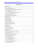
UMAC-CPCI Turbo CPU Board Hardware Reference Manual Table of Contents INTRODUCTION .......................................................................................................................................................1 Associated Manuals...................................................................................................................................................1 BOARD CONFIGURATION ........................................................................................
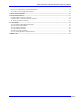
UMAC-CPCI Turbo CPU Board Hardware Reference Manual E25A, B, C: Flash Memory Firmware Bank Select ...............................................................................................13 W1: Flash IC Power Supply Select Jumper............................................................................................................14 CONNECTOR SUMMARY .....................................................................................................................................
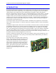
UMAC-CPCI Turbo CPU Board Hardware Reference Manual INTRODUCTION Delta Tau’s Compact UMAC systems provide a compact and clean integration of motion and I/O control for sophisticated automation equipment. The Compact UMAC CPU was previously called the UMACCPCI in previous revisions of this manual.
UMAC-CPCI Turbo CPU Board Hardware Reference Manual This picture shows a sample configuration of a Compact UMAC system, not installed in its rack. It consists of the following components: 1. Rack power supply (not a Delta Tau product) 2. Compact UMAC CPU board 3. Acc-11C Sinking I/O board 4. Acc-24C2A analog axis interface board 5. Acc-C8 8-slot Compact UBUS backplane. Note the pass-through connector on the back for field-wiring distribution.
UMAC-CPCI Turbo CPU Board Hardware Reference Manual Associated Manuals This document is the Hardware Reference Manual for the Compact UMAC Turbo CPU board for an Compact UMAC system. It describes the hardware features and provides setup instructions. Other manuals are needed as well to use the Compact UMAC system. Each accessory to the Compact UMAC Turbo CPU board has its own manual, describing its operation and any required software setup of the Turbo CPU.
UMAC-CPCI Turbo CPU Board Hardware Reference Manual BOARD CONFIGURATION The base version of the Compact UMAC Turbo CPU board provides a 1-slot 3U-format Eurocard board with: • 80 MHz DSP56303 CPU (120 MHz PMAC equivalent) • 128k x 24 SRAM compiled/assembled program memory (Opt. 5C0) • 128k x 24 SRAM user data memory (Opt. 5C0) • 1M x 8 flash memory for user backup & firmware (Opt.
UMAC-CPCI Turbo CPU Board Hardware Reference Manual The CPU is a DSP563xx IC as component U1. It is currently available only as an 80 MHz, 160 MHz or 240 MHz device. The compiled/assembled-program (P) memory SRAM ICs are located in U14, U15, and U16. These ICs form the active memory for the firmware, compiled PLCs, and user-written phase/servo algorithms.
UMAC-CPCI Turbo CPU Board Hardware Reference Manual Legacy Revision Memory Options (Rev 102 and below) • • • • Option 5C0 is the standard CPU and memory configuration. It is provided automatically if no Option 5xx is specified. It provides an 80 MHz DSP56303 CPU (120 MHz PMAC equivalent) with 8k x 24 of internal memory, an external 128k x 24 of compiled/assembled program memory, an external 128k x 24 of user data memory; and a 1M x 8 flash memory.
UMAC-CPCI Turbo CPU Board Hardware Reference Manual HARDWARE SETUP Clock-Source Jumpers In order to operate properly, the Turbo CPU board must receive servo and phase clock signals from a source external to the board. These clock signals can be brought into the board from one of three possible ports: the stack connector, the UBUS backplane connector, or the front-side main serial-port connector. Jumpers E1A and E1B must be configured properly for the clock source used.
UMAC-CPCI Turbo CPU Board Hardware Reference Manual Serial-Port Level Select Jumpers The standard serial port can be used for either RS-232 or RS-422 serial communications. To use RS-232, jumpers E17 and E18 should connect pins 1 and 2; to use RS-422, jumpers E17 and E18 should connect pins 2 and 3. The front-panel DB-9 serial connector provides only the RS-232 signals, so in order to use this connector, E17 and E18 must both connect pins 1 and 2.
UMAC-CPCI Turbo CPU Board Hardware Reference Manual CONNECTIONS In a typical installation, the Compact UMAC Turbo CPU board is simply slid into a slot of a 3U-Eurocard rack until it inserts into the mating connectors on the backplane board already installed in the rack. In actual operation, all signals to the board come into the CPU board through the backplane. (The frontpanel RS-232 connector is intended for test and debugging purposes.
UMAC-CPCI Turbo CPU Board Hardware Reference Manual Factory-Use Connectors There are several connectors on the interior of the board for factory setup and diagnostic use. These are not for customer use.
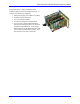
UMAC-CPCI Turbo CPU Board Hardware Reference Manual BOARD LAYOUT This diagram of the Compact UMAC Turbo CPU board shows the locations of the jumpers and connectors. Detailed information about each of the jumpers and connectors follows.
UMAC-CPCI Turbo CPU Board Hardware Reference Manual Legacy Revision Layout Diagram (rev 102 and below) 10 Board Layout
UMAC-CPCI Turbo CPU Board Hardware Reference Manual JUMPER DESCRIPTIONS Note: Pin 1 of an E-point is masked by an X and a bold square in white ink on the composite side, and by a square solder pad on the solder side. E0: Reset-Lock Enable (Factory Use Only) E Point and Physical Layout Location Description Jump pins 1 and 2 to lock the Compact UMAC Turbo CPU board in the reset state to permit installation of on-board logic. This setting for factory use only.
UMAC-CPCI Turbo CPU Board Hardware Reference Manual E3: Re-Initialization on Reset Control E Point and Physical Layout Location Description Default Remove jumper for normal reset mode (default). Jump pins 1 to 2 for re-initialization on reset.
UMAC-CPCI Turbo CPU Board Hardware Reference Manual E18A, B, C, D: Ethernet Communication Control E Point and Physical Layout 1 1 1 1 Location Description Jump 1 to 2 to Ethernet Connection to J7 front connector Jump 2-3 for Ethernet connection through back J2 connector E18D E18C E18B E18A Default Pins 1-2 jumpered E19: Watchdog Disable Jumper E Point and Physical Layout Location Description Jump pin 1 to 2 to disable Watchdog timer (for test purposes only.). Remove jumper to enable Watchdog timer.
UMAC-CPCI Turbo CPU Board Hardware Reference Manual W1: Flash IC Power Supply Select Jumper E Point and Physical Layout 14 Location Description Default B-1 (Note: This jumper is set at the factory and possibly hard soldered. Users should not change this jumper.) Jump pin 1 to 2 to select 3.3V supply for flash memory IC in U10. Jump pin 2 to 3 to select 5V supply for flash memory IC in U10. Setting dependent on flash IC used.
UMAC-CPCI Turbo CPU Board Hardware Reference Manual CONNECTOR SUMMARY Compact UBUS Backplane Connector J1: * Thru-Backplane Field Wiring Connector J2: * RS-232 Front-Panel Serial-Port Connector J4: * JTAG/OnCE (for factory use only): 10-pin IDC connector J5: JISP (for factory use only): 8-pin SIP connector J6: JISP_B (for factory use only) 8-pin SIP connector J10: First component-side stack connector to CPCI bridge board J11: First solder-side stack connector to CPCI bridge board J11A: First component-side
UMAC-CPCI Turbo CPU Board Hardware Reference Manual 16 Connector Summary
UMAC-CPCI Turbo CPU Board Hardware Reference Manual CONNECTOR PINOUTS Compact UBUS Connector (J1) Pinout Row Z A B C D E F 25 GND 5V 3.3V 5V GND 24 GND BD02 5V V(I/O) BD01 BD00 GND 23 GND 3.3V BD05 BD04 5V BD03 GND 22 GND BD09 BD08 3.3V BD07 BD06 GND 21 GND 3.3V BD13 BD12 BD11 BD10 GND 20 GND BD17 GND BD16 BD15 BD14 GND 19 GND 3.3V BD20 BD19 GND BD18 GND 18 GND BD23 GND 3.3V BD22 BD21 GND 17 GND 3.3V {BD26} {BD25} GND {BD24} GND 16 GND {BD30} GND {BD29} {BD28} {BD27} GND 15 GND 3.
UMAC-CPCI Turbo CPU Board Hardware Reference Manual Compact UMAC Turbo CPU Board J2 Connector Row Z A B C D E F 22 GND +5V GND 21 GND RxD/ CTS +5V TxD/ RTS GND 20 GND RDRD+ GND SDSD+ GND 19 GND CS+ CSGND RS+/ RSGND 18 GND DSR DTR INIT/ GND 17 GND SERVOSERVO+ PHASEPHASE+ GND 16 GND GND 15 GND AuxRxD/ AuxCTS AuxTxD/ AuxRTS GND 14 GND AuxDSR AuxDTR GND 13 GND USBDP (D+) GND USBDM (D-) GND 12 GND GND 11 GND EthTxF+ EthTxFEthRxF+ EthRxFGND 10 GND GND 9 GND GND 8 GND GND 7 GND GND 6 GND GND 5 GND GND 4 G
UMAC-CPCI Turbo CPU Board Hardware Reference Manual J4: RS-232 Serial Port Connector (DB-9S Connector) Pin # Symbol Function Description Notes 1 N.C. No connect 2 TXDOutput Send Data Low TRUE 3 RXDInput Receive Data Low TRUE 4 DSR Bidirect Data Set Ready Shorted to DTR 5 GND Common Compact UMAC Reference 6 DTR Bidirect Data Terminal Ready Shorted to DSR 7 CTS Input Clear to Send High TRUE 8 RTS Output Request to Send High TRUE 9 N.C.
UMAC-CPCI Turbo CPU Board Hardware Reference Manual 20 Connector Pinouts
UMAC-CPCI Turbo CPU Board Hardware Reference Manual ACCESSORIES The Compact UMAC Turbo CPU board is always used with accessory boards. Delta Tau provides several accessory boards in the Compact UMAC family that can be used with the CPU board; other parties may produce accessory boards as well. Each accessory board has its own hardware reference manual.
UMAC-CPCI Turbo CPU Board Hardware Reference Manual Acc-24C2 PWM Axis Board The Acc-24C2 PWM axis board provides the interface circuitry for four axes of purely digital control in a single slot, with direct PWM outputs, serial ADC inputs, quadrature encoder inputs, and input/output flags. Because of pin limitations on the J2 field wiring connector, signals that are differential on other Acc-24x2 boards are single-ended here.
UMAC-CPCI Turbo CPU Board Hardware Reference Manual SCHEMATICS DATA SYSTEMS INC. AND IS LOANED SUBJECT TO RETURN UPON THIS DOCUMENT IS THE CONFIDENTIAL PROPERTY OF DELTA TAU +3P3V C99 PHASE+ 10UF 16V (TANT) 3 OSC_OUT RP10B 3.3KSIP8I RP10C 5 10 GND 7 +3P3V RP10D SERVO+ 6 3.3KSIP8I 8 SCK0 SC02 RD- .1UF BA05 BA06 BA07 ISPENA15 BA09 6 7 8 MODE BA08 WR- HSIP8NO5 BA13 +3P3V BA12 BA10 BA11 BA14 C25 C21 .01UF GND .1UF BA15 GND SERVORP11C BA06 +3P3V 22pf 7 BA11 1 RP1D 3.
UMAC-CPCI Turbo CPU Board Hardware Reference Manual THIS DOCUMENT IS THE CONFIDENTIAL PROPERTY OF DELTA TAU DATA SYSTEMS INC. AND IS LOANED SUBJECT TO RETURN UPON DEMAND. TITLE TO THIS DOCUMENT IS NEVER SOLD OR TRANSFERRED FOR ANY REASON. THIS DOCUMENT IS TO BE USED ONLY PURSUANT TO WRITTEN LICENSE OR WRITTEN INSTRUCTIONS OF DELTA TAU DATA SYSTEMS INC.
UMAC-CPCI Turbo CPU Board Hardware Reference Manual K1 R31 3 5 1 1 RAMCSRAMOE- GND 1.5K USBRST- C160 GND +3P3V NMI- .1UF+3P3V NMI- FBR12ND05 2N7002 +5V REMOVE `E11' FOR U65 U62 GND A C GND GND B D GND 8 7 6 5 NC7SZ02M5 (SOT32-5) EQU_1 2 PSEN- WDO WDO 1 USBRD- -5V +12V -12V 4 2 VREF GND +5V -5V +12V -12V DIN NC7SZ08M5 GND SN75240PW +5V 14 13 12 11 10 9 8 VDD OUT1 OUT2 OUT3 OUT4 DOUT PGND 1 E11 WD_NO INIT1 GND 4 2 GND Q6 3 SOT23 +5V 2N7002 10 1 0.