^1 HARDWARE REFERENCE MANUAL ^2UMAC CPCI Accessory Cx ^3 Compact UBUS Backplane Boards ^4 4Ax-603617-xHxx ^5 January 28, 2003 Single Source Machine Control Power // Flexibility // Ease of Use 21314 Lassen Street Chatsworth, CA 91311 // Tel. (818) 998-2095 Fax. (818) 998-7807 // www.deltatau.
Copyright Information © 2003 Delta Tau Data Systems, Inc. All rights reserved. This document is furnished for the customers of Delta Tau Data Systems, Inc. Other uses are unauthorized without written permission of Delta Tau Data Systems, Inc. Information contained in this manual may be updated from time-to-time due to product improvements, etc., and may not conform in every respect to former issues. To report errors or inconsistencies, call or email: Delta Tau Data Systems, Inc.
UMAC CPCI Accessory Cx Family Table of Contents INTRODUCTION .......................................................................................................................................................1 CONNECTIONS .........................................................................................................................................................3 Compact UBUS Connectors...........................................................................................................
UMAC CPCI Accessory Cx Family ii Table of Contents
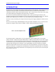
UMAC CPCI Accessory Cx Family INTRODUCTION The Acc-Cx family of backplane boards for the UMAC CPCI controller provides the connection means for field wiring, power supply and interboard communications for this controller. These backplane boards implement the Compact UBUS communications bus that enables the UMAC CPCI CPU board to communicate with the motion and I/O interface boards. The x in the accessory name refers to the number of Compact UBUS slots (including the slot for the CPU) on the board.
UMAC CPCI Accessory Cx Family 2 Introduction
UMAC CPCI Accessory Cx Family CONNECTIONS In a typical configuration, the Acc-Cx Compact UBUS backplane board is installed into a standard 3Uformat Eurorack with screws and the 3U-format UMAC CPCI boards are slid into the rack so that their J1 and J2 rear connectors mate with the P1-n and P2-n connectors on the front side of the backplane board. A rack-mounted power supply is installed into the P47-style power connector and the power source is connected into the rear-side J1 connector.
UMAC CPCI Accessory Cx Family 4 Connections
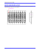
UMAC CPCI Accessory Cx Family BACKPLANE BOARD LAYOUT This diagram of the UMAC CPCI Acc-C8 backplane board shows the locations of the connectors.
UMAC CPCI Accessory Cx Family 6 Backplane Board Layout
UMAC CPCI Accessory Cx Family CONNECTOR SUMMARY P1-n: P2-n: P{x+1} J1: J2: Compact UBUS Backplane Connectors Thru-Backplane Field Wiring Connectors Rack-Mounted Power Supply Connector Line Supply Input Connector Alternate Analog Power Connector Connector Summary 7
UMAC CPCI Accessory Cx Family 8 Connector Summary
UMAC CPCI Accessory Cx Family CONNECTOR PINOUTS Compact UBUS Connector (P1-n) Pin-Out For a backplane board with x data slots, the connector P1-n (n = 1 to x) is the Compact-UBUS connector for each 3U-format board. Like signals on all P1-n connectors are bussed together. Row Z A B C D E F 25 GND 5V 3.3V 5V GND 24 GND BD02 5V V(I/O) BD01 BD00 GND 23 GND 3.3V BD05 BD04 5V BD03 GND 22 GND BD09 BD08 3.3V BD07 BD06 GND 21 GND 3.3V BD13 BD12 BD11 BD10 GND 20 GND BD17 GND BD16 BD15 BD14 GND 19 GND 3.
UMAC CPCI Accessory Cx Family Pass-Through (P2-n) Connectors For a backplane board with x data slots, the connector P2-n (n = 1 to x) is the pass-through connector for field wiring for each 3U-format board.
UMAC CPCI Accessory Cx Family P{x+1}: Power Supply (P47-Style) Connector For a backplane board with x data slots, the connector P{x+1} (e.g. P9 for the Acc-C8 8-slot board) is the power-supply connector. Pins 1-20: Size 16 Power-Supply Outputs to Backplane Pin No. Description Pin No. 1 2 3 4 5 6 7 8 9 10 +5V (V1) +5V (V1) +5V (V1) +5V (V1) +5V/+3.3V Return (ground plane) +5V/+3.3V Return (ground plane) +5V/+3.3V Return (ground plane) +5V/+3.3V Return (ground plane) +5V/+3.3V Return (ground plane) +5V/+3.
UMAC CPCI Accessory Cx Family J1 Line Supply Input Connector Pin # Symbol Function 1 2 CHASSIS GND ACN / DC IN+ EARTH INPUT Description Notes Connection to earth ground Important safety connection Neutral input for AC supply; Signal level and type dependent on power positive input for DC supply supply installed. 3 ACL / DC ININPUT Line input for AC supply; Signal level and type dependent on power negative input for DC supply supply installed.