
Reference Manual

Turbo PMAC/PMAC2 Software Reference
Turbo PMAC Global I-Variables 190
the same function for a hardware run command as the B command does for a software run command (R).
It is intended primarily for stand-alone Turbo PMAC applications. The first use of a B command from a
host computer for this coordinate system overrides this parameter.
Isx92 Coordinate System ‘x’ Move Blend Disable
Range: 0 .. 1
Units: none
Default: 0
Isx92 controls whether programmed moves for Coordinate System ‘x’ are automatically blended or not.
If Isx92 is set to 0, programmed moves that can be blended together – LINEAR, SPLINE, and CIRCLE-
mode – are blended together with no intervening stop, unless Isx83 is set to 1 non-zero value and the
corner formed at the juncture of LINEAR and/or CIRCLE-mode moves is sharper than the Isx83
threshold. Upcoming moves are calculated during the current moves.
If Isx92 is set to 1, even moves that can be blended together are not blended. The commanded trajectory
is brought to a stop at the end of each programmed move. If Isx81 is greater than 0, Turbo PMAC then
verifies that all motors in the coordinate system are “in position”. Next, a dwell of Isx82 real-time
interrupt periods is executed. After the dwell, the next move is calculated and executed.
Isx92 is only evaluated when the R or S command is given to start program execution. It is used to set the
coordinate system’s “continuous motion request” (CMR) status/control bit, which is checked each time a
blending decision is to be made. (If Isx92 is 1, the CMR bit is set to 0; if Isx92 is 0, the CMR bit is set to
1.) To change the mode of operation while the program is running, the CMR bit must be changed directly
using an M-variable. Msx84 is the suggested M-variable for this bit for Coordinate System ‘x’ (M5184-
>X:$002040,4 for C.S. 1).
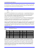
Isx93 Coordinate System x Time Base Control Address
Range: $000000 - $FFFFFF
Units: Turbo PMAC X-Addresses
Default:
I-Var.
Default
Register
I-Var.
Default
Register
I5193
$002000
C.S.1 ‘%’ Cmd. Reg.
I5993
$002800
C.S.9 ‘%’ Cmd. Reg.
I5293
$002100
C.S.2 ‘%’ Cmd. Reg.
I6093
$002900
C.S.10 ‘%’ Cmd. Reg.
I5393
$002200
C.S.1 ‘%’ Cmd. Reg.
I6193
$002A00
C.S.11 ‘%’ Cmd. Reg.
I5493
$002300
C.S.2 ‘%’ Cmd. Reg.
I6293
$002B00
C.S.12 ‘%’ Cmd. Reg.
I5593
$002400
C.S.5 ‘%’ Cmd. Reg.
I6393
$002C00
C.S.13 ‘%’ Cmd. Reg.
I5693
$002500
C.S.6 ‘%’ Cmd. Reg.
I6493
$002D00
C.S.14 ‘%’ Cmd. Reg.
I5793
$002600
C.S.7 ‘%’ Cmd. Reg.
I6593
$002E00
C.S.15 ‘%’ Cmd. Reg.
I5893
$002700
C.S.8 ‘%’ Cmd. Reg.
I6693
$002F00
C.S.16 ‘%’ Cmd. Reg.
Isx93 tells Coordinate System x where to look for its time base control (feedrate override) information by
specifying the address of the register that will be used. The default value of this parameter for each
coordinate system (see above) specifies the register that responds to on-line % commands. If the time
base is left alone, or is under host or programmatic control, this parameter should be left at the default.
Alternatively, if the time base is controlled externally from a frequency or voltage, usually the register
containing the time-base information will be in the conversion table (which starts at address $003500).
If another register is to be used for the time base, it must have the units of I10 so that 8,388,608 (2
23
)
indicates 1 msec between servo interrupts. See the instructions for using an external time base, under
Synchronizing PMAC to External Events.