
Reference Manual


Turbo PMAC/PMAC2 Software Reference
Turbo PMAC Global I-Variables 220
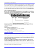
The first 1 creates a rising edge on the ADC_STROB output that is typically used as a start-convert
signal. Some A/D converters just need this rising edge for the conversion; others need the signal to stay
high all of the way through the conversion. The LSB of I7m06 should always be set to 0 so that a rising
edge is created on the next cycle. The default I7m06 value of $FFFFFE is suitable for virtually all A/D
converters.
The A/D converters used on matching Delta Tau products just need the rising edge at the start of a
conversion cycle; this permits intermediate bits in the data stream to be used as special control bits. Delta
Tau’s Acc-8T Supplemental Flag Multiplexer Board uses these bits to control the multiplexing; Delta
Tau’s Acc-8K1 Fanuc C/S-Series PWM Interface Board uses these bits to control the magnetic contactors
on the drives.
For accessory boards in which alternate addressing of the Servo IC is used (labeled Servo IC m*), this
function is controlled by I7m56, not I7m06.
I7m07 Servo IC m Phase/Servo Clock Direction
Range: 0 - 3
Units: None
Default: I7007 = 0 (non-Ultralite); = 3 (Ultralite)
I7107 – I7907 = 3
I7m07 controls whether Servo IC m uses its own internally generated Phase and Servo clock signals as
controlled by I7m00, I7m01, and I7m02, or whether it uses Phase and Servo clock signals from an outside
source.
In any Turbo PMAC2 system, there must be either one and only one source of servo and phase clock
signals for the system – one of the Servo ICs or MACRO ICs, or a source external to the system. Only in
a 3U-format Turbo PMAC2 system (UMAC Turbo or 3U Turbo Stack) can the system clock signals
come from an accessory board. In all other Turbo PMAC2 systems, the system clock signals must come
from and IC on the base PMAC2 boards, or be brought from an external source through the serial port.
I7m07 is a 2-bit value. Bit 0 is set to 0 for the IC to use its own Phase clock signal and output it; it is set
to 1 to use an externally input Phase clock signal. Bit 1 is set to 1 for the IC to use its own Servo clock
signal and output it; it is set to 1 to use an externally input Servo clock signal. This yields four possible
values for I7m07:
I7m07 = 0: Internal Phase clock; internal Servo clock
I7m07 = 1: External Phase clock; internal Servo clock
I7m07 = 2: Internal Phase clock; external Servo clock
I7m07 = 3: External Phase clock; external Servo clock
In all normal use, I7m07 is either set to 0 (on at most one IC) or 3 (on all the other ICs).
In general, Servo IC 0 or MACRO IC 0 (on an Ultralite board that has no Servo ICs) will be used to
generate Phase and Servo clock signals for the entire PMAC systems, so I7007 is set to 0 (or I6807 on an
Ultralite board), and I7107 through I7907 are set to 3.
During re-initialization, Turbo PMAC2 determines which IC it will use as the source of its system Phase
and Servo clock signals, setting I19 to the number of the clock-direction I-variable whose IC is selected as
the source. This clock-direction I-variable is then automatically set to 0; all other clock-direction I-
variables are set to 1 or 3. Most users will never change these settings.
When a clock-direction I-variable is commanded to its default value (e.g. I7207=*), Turbo PMAC2
looks to the value of I19 to determine whether this I-variable is set to 0 or 3.
On the reset of a 3U-format Turbo PMAC2 system (UMAC Turbo or 3U Turbo Stack), the values set for
these I-variables are determined by the saved value of I19, and not by the saved values of these I-
variables themselves. On these systems, to change which IC is the source of the system clocks, change
the value of I19, save this setting, and reset the card.