
Reference Manual

Turbo PMAC/PMAC2 Software Reference
Turbo PMAC Global I-Variables 222
In the pulse-and-direction decode modes, the Servo IC is expecting the pulse train on CHAn, and the
direction (sign) signal on CHBn. If the signal is unidirectional, the CHBn line can be allowed to pull up
to a high state, or it can be hardwired to a high or low state.
If I7mn0 is set to 8, the decoder inputs the pulse and direction signal generated by Channel n's pulse
frequency modulator (PFM) output circuitry. This permits the PMAC2 to create a phantom closed loop
when driving an open-loop stepper system. No jumpers or cables are needed to do this; the connection is
entirely within the Servo IC. The counter polarity automatically matches the PFM output polarity.
If I7mn0 is set to 11 or 15, Channel n is expecting three Hall-sensor format inputs on CHAn, CHBn, and
CHCn, each with approximately 50% duty cycle, and approximately one-third (120
o
e) of a cycle out of
phase with each other. The decode circuitry will generate one count on each edge of each signal, yielding
6 counts per signal cycle (x6 decode). The difference between 11 and 15 is which direction of signal
causes the counter to count up.
If I7mn0 is set to 12, the timer circuitry is set up to read magnetostrictive linear displacement transducers
(MLDTs) such as Temposonics
TM
. In this mode, the timer is cleared when the PFM circuitry sends out
the excitation pulse to the sensor on PULSEn, and it is latched into the memory-mapped register when the
excitation pulse is received on CHAn.
I7mn1 Servo IC m Channel n Position Compare Channel Select
Range: 0 - 1
Units: None
Default: 0
I7mn1 controls which channel’s encoder counter is tied to the position compare circuitry for Channel n on
a PMAC2-style Servo IC m. It has the following possible settings:
I7mn1 = 0: Use Channel n encoder counter for position compare function
I7mn1 = 1: Use Channel 1 encoder counter on IC for position compare function
When I7mn1 is set to 0, Channel n’s position compare registers are tied to the channel's own encoder
counter, and the position compare signal appears only on the EQU output for that channel.
When I7mn1 is set to 1, the channel's position compare register is tied to the first encoder counter on the
Servo IC, and the position compare signal appears both on Channel n’s EQU output, and combined into
the EQU output for Channel 1 on the Servo IC (EQU1 or EQU5 on the board); executed as a logical
AND.
I7m11 performs no effective function, so is always 1. It cannot be set to 0.
I7mn2 Servo IC m Channel n Capture Control
Range: 0 - 15
Units: none
Default: 1
I7mn2 determines which input signal or combination of signals for Channel n of a PMAC2-style Servo IC
m, and which polarity, triggers a hardware position capture of the counter for Encoder n. If a flag input
(home, limit, or user) is used, I7mn3 determines which flag. Proper setup of this variable is essential for a
successful homing search move or other move-until-trigger for the Motor xx using Channel n for its
position-loop feedback and flags if the super-accurate hardware position capture function is used. If
Ixx97 is at its default value of 0 to select hardware capture and trigger, this variable must be set up
properly.
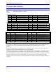
The following settings of I7mn2 may be used:
I7mn2 = 0: Immediate capture
I7mn2 = 1: Capture on Index (CHCn) high
I7mn2 = 2: Capture on Flag n high