
Reference Manual


Turbo PMAC/PMAC2 Software Reference
UMAC Turbo Suggested M-Variable Definitions 677
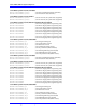
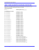
Acc-5E JTHW Thumbwheel Multiplexer Port M-Variables
M40->Y:$078402,8 ; SEL0 Line; J2 Pin 4
M41->Y:$078402,9 ; SEL1 Line; J2 Pin 6
M42->Y:$078402,10 ; SEL2 Line; J2 Pin 8
M43->Y:$078402,11 ; SEL3 Line; J2 Pin 10
M44->Y:$078402,12 ; SEL4 Line; J2 Pin 12
M45->Y:$078402,13 ; SEL5 Line; J2 Pin 14
M46->Y:$078402,14 ; SEL6 Line; J2 Pin 16
M47->Y:$078402,15 ; SEL7 Line; J2 Pin 18
M48->Y:$078402,8,8,U ; SEL0-7 Lines treated as a byte
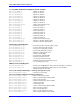
M50->Y:$078402,0 ; DAT0 Line; J2 Pin 3
M51->Y:$078402,1 ; DAT1 Line; J2 Pin 5
M52->Y:$078402,2 ; DAT2 Line; J2 Pin 7
M53->Y:$078402,3 ; DAT3 Line; J2 Pin 9
M54->Y:$078402,4 ; DAT4 Line; J2 Pin 11
M55->Y:$078402,5 ; DAT5 Line; J2 Pin 13
M56->Y:$078402,6 ; DAT6 Line; J2 Pin 15
M57->Y:$078402,7 ; DAT7 Line; J2 Pin 17
M58->Y:$078402,0,8,U ; DAT0-7 Lines treated as a byte
M60->X:$078402,0,8 ; Direction control for DAT0 to DAT7
M62->X:$078402,8,8 ; Direction control for SEL0 to SEL7
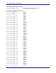
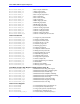
Miscellaneous Global Registers
M70->X:$FFFF8C,0,24 ; Time between phase interrupts (CPU cycles/2)
M71->X:$000037,0,24 ; Time for phase tasks (CPU cycles/2)
M72->Y:$000037,0,24 ; Time for servo tasks (CPU cycles/2)
M73->X:$00000B,0,24 ; Time for RTI tasks (CPU cycles/2)
M80->X:$000025,0,24 ; Minimum watchdog timer count
M81->X:$000024,0,24 ; Pointer to display buffer
M82->Y:$001080,0,8 ; First character of display buffer
M83->X:$000006,12,1 ; Firmware checksum error bit
M84->X:$000006,13,1 ; Any memory checksum error bit
M85->X:$000006,5,1 ; MACRO auxiliary communications error bit
M86->X:$000006,6,1 ; Acc-34 serial parity error bit
DPRAM Active Setup Registers
M93->X:$070009,0,8 ; PC/104 Active DPRAM Base Address bits A23-A16 (Bits 0-7 from I93)
M94->X:$07000A,0,8 ; PC/104 Active DPRAM Base Address bits A15-A14, Enable &
; Bank Select (Bits 0-7 from I94)
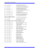
Servo Cycle Counter (Read Only) -- counts up once per servo cycle
M100->X:$000000,0,24,S ; 24-bit servo cycle counter
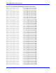
Servo IC 2 Channel 1 Registers (usually for Motor #1)
M101->X:$078201,0,24,S ; ENC1 24-bit counter position
M102->Y:$078202,8,16,S ; OUT1A command value; DAC or PWM
M103->X:$078203,0,24,S ; ENC1 captured position
M104->Y:$078203,8,16,S ; OUT1B command value; DAC or PWM
M105->Y:$078205,8,16,S ; ADC1A input value
M106->Y:$078206,8,16,S ; ADC1B input value
M107->Y:$078204,8,16,S ; OUT1C command value; PFM or PWM
M108->Y:$078207,0,24,S ; ENC1 compare A position
M109->X:$078207,0,24,S ; ENC1 compare B position
M110->X:$078206,0,24,S ; ENC1 compare autoincrement value
M111->X:$078205,11 ; ENC1 compare initial state write enable