
User's Manual


Turbo PMAC User Manual
Setting Up a Coordinate System 263
Creating the Inverse-Kinematic Program
The on-line OPEN INVERSE command opens the inverse-kinematic buffer for the addressed coordinate
system for entry. The on-line CLEAR command erases any existing contents of that buffer. Subsequently,
any math or logic program command sent to Turbo PMAC that is legal for a PLC program (this does not
include ADDRESS, DISPLAY, CMDx, or SENDx) will be entered into the open buffer. The on-line CLOSE
command stops entry into the buffer.
Before any execution of the inverse-kinematic program, Turbo PMAC will place the present axis target
positions for each axis in the coordinate system into variables in the range Q1 – Q9 for the coordinate
system. These are floating-point values, in engineering units. The program can then use these variables as
the “inputs” to the calculations. The following table shows the variable for each axis:
Axis-
Position Q-
Variable
Axis
Letter
Axis-
Position Q-
Variable
Axis
Letter
Axis-
Position Q-
Variable
Axis
Letter
Q1 A Q4 U Q7 X
Q2 B Q5 V Q8 Y
Q3 C Q6 W Q9 Z
After any execution of the inverse-kinematic program, Turbo PMAC will read the values in those variables
Pxx (P1 – P32) that correspond to Motors xx in the coordinate system with axis-definition statements of
#xx->I. These are floating-point values, and Turbo PMAC expects to find them in the raw units of
“counts.” Turbo PMAC will automatically copy these values into the target position registers for these
motors (suggested M-variable Mxx63), where they are used for the fine interpolation of these motors.
There can be other motors in the coordinate system that are not defined as inverse-kinematic axes; these
motors get their position values directly from the axis-definition statement and are not affected by the
inverse-kinematic program.
The basic purpose of the inverse-kinematic program, then, is to take the tip-position values found in Q1 –
Q9 for the axes used in the coordinate system, compute the matching joint-coordinate values, and place
them in variables in the P1 – P32 range.
Example
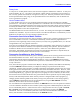
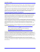
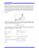
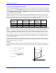
Continuing with our example of the two-axis shoulder-elbow robot, and for simplicity’s sake limiting
ourselves to positive values of B (the right-armed case), we can write our inverse-kinematic equations as
follows:
C)CA(A
2
Y
2
X
1
L2
2
2
L
2
1
L
2
Y
2
X
1
cosC
)X,Y(2tanaCA
2
L
1
L2
2
2
L
2
1
L
2
Y
2
X
1
cosB
−+=
+
−++
−
+=
=+
−−+
−
+=
(X, Y)
Y
L2
√
(X
2
+Y
2
)
B
L1
C
A
X