
User's Manual


Turbo PMAC User Manual
Turbo PMAC System Configuration and Auto Configuration 25
• Output to PWM circuits
• Communication over MACRO ring
The software tasks that are driven by the phase and servo clock signals include:
• Digital current loop closure (phase clock)
• Motor phase commutation (phase clock)
• Demuxing of muxed A/D converters (phase clock)
• Encoder conversion table pre-processing (servo clock)
• Trajectory interpolation (servo clock)
• Position/velocity loop closure (servo clock and Ixx60)
• PLC 0 and PLCC 0 execution (servo clock and I8)
• Checking for motion program move planning (servo clock and I8)
The sections on commutation and servo-loop closure discuss the selection of optimal frequencies for these
signals. In general, higher frequencies can lead to higher performance (although there are points of
diminishing returns, and other system limitations can cap performance no matter how fast the Turbo
PMAC is running), at the cost of increase processor usage.
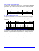
Setting Turbo PMAC Phase and Servo Clock Frequencies
On a Turbo PMAC controller, the system clock frequencies are determined by the setting of E-point
jumpers. While some E-point numbers are specific to a particular controller, the clock-frequency jumper
numbers are common to all Turbo PMAC controllers and so can be summarized here. Consult the
Hardware Reference Manual for the particular controller to get the location for these jumpers on the
board.
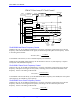
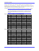
PMAC(1) Clock Dividing Circuitry
E34A
E34
E35
E36
E37
1/16
1
2
3
1/2
1/8
1/4
Crystal
Oscillator
Encoder Sample Clock
(SCLK)
DAC/ADC Clock
(DCLK)
1/4
Analog Channel Select
(ASEL)
1/17
E33
E32
E31
E30
E29
1/16
1/2
1/8
1/4
Servo Clock
(Servo)
1/n
E3
E4
E5
E6
n = 1 to 16
Phase Clock
(Phase)
19.6608 MHz
E98
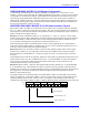
E98 DCLK Frequency Control
E98 controls the frequency of the DCLK clock signal that controls the bit rate into all the D/A converters
on the board and out of all the Acc-28 A/D converters connected to the board. The factory default setting
connects pins 1 and 2 of E98, setting a DCLK frequency of 2.46 MHz. It should be left in this setting
unless any Acc-28 A/D converter is connected to the board. In this case, the jumper should be moved to
connect pins 2 and 3, reducing the frequency to 1.23 MHz.