
User's Manual


Turbo PMAC User Manual
Setting Up Feedback and Master Position Sensors 57
Setting up Sinusoidal Encoders
Turbo PMAC systems can accept signals from sinusoidal (sine/cosine) encoders and generate position
data of very high resolution. This is done through special accessory boards and dedicated firmware
algorithms. Presently there are two classes of interpolators: low-resolution ones producing 128 or 256
states per line, and high-resolution ones producing 4096 states per line.
Note:
Many Turbo PMAC users will utilize sinusoidal encoders for position feedback,
but with the interpolation function performed in an external interpolator module,
which generates a high-frequency synthesized digital quadrature signal for the
controller that is connected to the Turbo PMAC. In this case, the Turbo PMAC
treats the feedback just as if a real digital quadrature encoder were used.
Hardware Setup
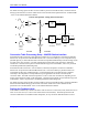
The sine and cosine channels of the encoder are connected either as single-ended or differential inputs
(differential is strongly recommended) into the interpolator accessory according to the instructions for the
interpolator. Optionally, the index channel may be connected as well. Consult the hardware reference
manual of the particular accessory for details.
If connecting a low-resolution interpolator into a Turbo PMAC or accessory with PMAC-style Servo ICs,
the fractional-count data is brought into the Servo IC at TTL levels on the flag signals for the channel
numbered one higher than that of the encoder signal itself. Normally, these signals are 12-24V isolated
flags to use the interpolator, the isolators must be removed and replaced with conducting shunts.
Turbo PMAC Hardware-Control Parameter Setup
Encoder Sampling Clock Frequency: E34 – E38, I7m03, MI903, MI907
For the low-resolution interpolator, the Turbo PMAC’s SCLK encoder-sampling clock drives the analog
conversion on the interpolator, as well as the encoder functions in the Servo IC. This clock must be set to
a frequency of 2.46 MHz. If the interpolator is connected to a Turbo PMAC or accessory with PMAC-
style Servo ICs, this frequency is set by jumpers on the PMAC or accessory: of the E-points E34 – E38,
there should only be a jumper on E36.
If the low-resolution interpolator is connected to a Turbo PMAC2 or accessory with PMAC2-style Servo
ICs, Servo IC m’s variable I7m03 sets this frequency. If it is connected into a MACRO Station, Station
variable MI903 or MI907 sets this frequency. These variables also set other clock frequencies, but if the
other frequencies are left at their default (as they usually are), setting the SCLK frequency to 2.46 MHz
simply requires changing the variable value from its default of 2258 to 2260.
For an Acc-51x high-resolution interpolator, the SCLK signal just drives the sampling of the synthesized
quadrature in the interpolator’s own Servo IC. The default frequency of 9.83 MHz is virtually always
fine. On the Acc-51P, the frequency is set permanently to this value. On high-resolution interpolators
with PMAC2-style Servo ICs (e.g. Acc-51E, Acc-51C), IC variable I7m03 sets this frequency if the
interpolator is connected directly to a Turbo PMAC, or by MACRO Station variable MI903 or MI907 if
the interpolator is installed in a MACRO Station.
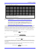
Encoder Decode Control: I7mn0, MI910
Both styles of interpolator create a digital quadrature signal from the sine/cosine inputs. This digital
signal goes into the encoder decoding and count circuitry to produce the whole-count data. To match the
whole-count and fractional count resolution properly, the decode-control variable must be set up to times-
4 quadrature decode. This variable is I7mn0 for Servo IC m Channel n in a Turbo PMAC system. On a
MACRO Station, it is node-specific variable MI910.