
User's Manual


Turbo PMAC User Manual
Basic Motor Setup 73
Motor Address Setup Parameters
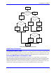
Each Turbo PMAC motor has several address I-variables that tell the motor what registers to use for its
inputs and outputs. Each of these variables contains the Turbo PMAC address of the register for the
particular function. This provides a mapping between the motor calculation registers and the different
types of servo I/O registers (encoders, D/A converters, flags, etc.) used for the physical interface. By
providing a user-settable mapping, Turbo PMAC makes it very easy to utilize different types of feedback
and output signals for each motor.
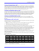
The following diagram shows how this mapping works for a motor directly accessing servo I/O registers
(without MACRO):
PMAC Direct Register Mapping
Status
ADC A
ADC B
Encoder
Flags
Current
Feedback
Signals
Position
Feedback Signal
Output A
Output B
Output C
Control
DAC, PWM
DAC, PWM
PFM, PWM
Amp Enable
Encoder
Conversion
Table
Motor x
Calculation
Registers
Ix25Ix82
Ix03
Ix04
Ix83
Ix25
Ix02
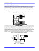
This next diagram shows the three-stage process to map between the motor calculation registers and the
servo I/O registers in a MACRO Station over a MACRO ring. The motor address I-variables specify the
first stage only – the mapping between the motor calculation registers and the Turbo PMAC’s own
MACRO node registers. The second step – the mapping between the Turbo PMAC’s MACRO node
registers and the MACRO Station’s MACRO node registers – is covered in the Basic Setup section (and
in the MACRO Station manuals). The third step – the mapping between the MACRO Station’s MACRO
node registers – is covered in the appropriate section of this manual (and in the MACRO Station
manuals). Once this mapping is set up, the motor will operate just as it would with a direct connection.
MACRO Ring
Connection
PMAC / MACRO Station Register Mapping
Motor x
Calculation
Registers
PMAC
MACRO Node
n Registers
MACRO Station
Machine Interface
Channel x Registers
MACRO Station
Node n
Registers
Servo &
Commutation
Address
I-variables
Channel
Interface Signals
Station SW1 Setting,
Conversion Table,
M110x
I996 bits 20-23 = Station SW2 Setting
Turbo: I6841, I6891, I6941, I6991 bits 20-23 = Station SW2 Setting
PMAC Node n = Station Node n
PMAC MACRO Station