
User's Manual

Turbo PMAC PCI HRM
Main Board E-Point Descriptions 25
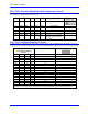
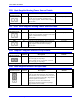
E85: Host-Supplied Analog Power Source Enable
E Point and
Physical Layout
Location Description Default
E85
C5 Jump pin 1 to pin 2 to allow A+14V to come
from PC bus (ties amplifier and PMAC PCI
power supply together. Defeats OPTO coupling.)
Also see E90.
No jumper
Note: If E85 is changed, E88 and E87 must also be changed.
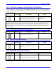
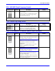
E87 - E88: Host-Supplied Analog Power Source Enable
E Point and
Physical Layout
Location Description Default
E87
C5 Jump pin 1 to pin 2 to allow AGND to come
from PC bus (ties amplifier and PMAC PCI GND
together. Defeats OPTO coupling.)
Also see E90.
No jumper
Note: If E87 is changed, E85 and E88 must also be changed.
E88
B2 Jump pin 1 to pin 2 to allow A-14V to come from
PC bus (ties amplifier and PMAC PCI power
supply together. Defeats OPTO coupling.)
Also see E90.
No jumper
Note: If E88 is changed; E87 and E85 must also be changed.
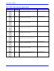
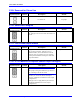
E89: Amplifier-Supplied Switch Pull-Up Enable
E Point and
Physical Layout
Location Description Default
E89
B5 Jump pin 1 to 2 to use A+15V on J8 (JMACH1)
pin 59 as supply for input flags.
Remove jumper to use A+15V/OPT+V from J7
pin 59 as supply for input flags.
Jumper installed
Note: This jumper setting is only relevant if E90 connects pin 1 to 2.
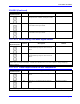
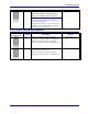
E90: Host-Supplied Switch Pull-Up Enable
E Point and
Physical Layout
Location Description Default
E90
B5 Jump pin 1 to 2 to use A+15V from J8 pin 59 as
supply for input flags (E89 ON) {flags should be
tied to AGND} or A+15V/OPT+V from J7 pin 59
as supply for input flags (E89 OFF) {flags should
be tied to separate 0V reference}.
Jump pin 2 to 3 to use +12V from PC bus
connector P1-pin B09 as supply for input flags
{flags should be tied to GND}.
1-2 Jumper installed
See also E85, E87, E88 and PMAC Opto-isolation diagram