^1 HARDWARE REFERENCE MANUAL ^2 PMAC VME ^3 Programmable Multi-Axis Controller ^4 4Ax-602203-xHxx ^5 November 4, 2004 Single Source Machine Control Power // Flexibility // Ease of Use 21314 Lassen Street Chatsworth, CA 91311 // Tel. (818) 998-2095 Fax. (818) 998-7807 // www.deltatau.
Copyright Information © 2003 Delta Tau Data Systems, Inc. All rights reserved. This document is furnished for the customers of Delta Tau Data Systems, Inc. Other uses are unauthorized without written permission of Delta Tau Data Systems, Inc. Information contained in this manual may be updated from time-to-time due to product improvements, etc., and may not conform in every respect to former issues. To report errors or inconsistencies, call or email: Delta Tau Data Systems, Inc.
PMAC VME Hardware Reference Manual Table of Contents PMAC VME E-POINT DESCRIPTIONS ................................................................................................................1 PMAC VME Bottom Board ......................................................................................................................................1 E1 - E2: Machine Output Supply Voltage Configure............................................................................................
PMAC VME Hardware Reference Manual J5 (JOPT)/OPTO I/O..........................................................................................................................................17 J6 (JXIO)/Expansion Board................................................................................................................................17 J7 (JEQU)/Position Compare.............................................................................................................................
PMAC VME Hardware Reference Manual Accessory 24: Axis Expansion Board ................................................................................................................42 Accessory 25: Extended Servo Algorithm Tuning Software ..............................................................................43 Accessory 26A: Serial Communications Converter...........................................................................................43 Accessory 27: Optically Isolated I/O Board .......
PMAC VME Hardware Reference Manual iv Table of Contents
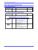
PMAC VME Hardware Reference Manual PMAC VME E-POINT DESCRIPTIONS PMAC VME Bottom Board E Point and Physical Layout Location Description Default E0 B5 For future use. No jumper E1 - E2: Machine Output Supply Voltage Configure E Point and Physical Layout Location Description Default CAUTION: The jumper settings for both E1 and E2 must match the type of driver IC, or damage to the IC will result.
PMAC VME Hardware Reference Manual E3 - E6: Servo Clock Frequency Control The servo clock (which determines how often the servo loop is closed) is derived from the phase clock (see E29 - E33) through a "divide-by-N" counter. Jumpers E3 through E6 control this dividing function.
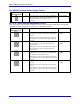
PMAC VME Hardware Reference Manual E8: RS232 Converter Power Supply Control E Point and Physical Layout Location Description E8 A4 Jump pin 1 to 2 to apply +5V to J4 pin 2 (JRS422); this can be used to power optional RS422 to RS232 converter module which requires +5V for operation. Default Jumper installed E9 - E16: Serial Interface Handshake Control E9 to E16 jumpers control whether the RS-422 serial port will be in DCE or DTE format.
PMAC VME Hardware Reference Manual E17A-E17D: Amplifier-Enable/Direction Polarity Control E Point and Physical Layout Location Description Default E17A B2 Jump 1-2 for high TRUE AENA (1-4). Remove jumper for low TRUE AENA (1-4). No jumper installed E17B C2 Jump 1-2 for high TRUE AENA (1-4). Remove jumper for low TRUE AENA (1-4). No jumper installed E17C C2 Jump 1-2 for high TRUE AENA (1-4). Remove jumper for low TRUE AENA (1-4).
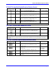
PMAC VME Hardware Reference Manual E28: Warning Following Error/Watchdog Timer Signal Control E Point and Physical Layout Location Description Default E28 B3 Jump pin 1 to 2 to allow warning following error (Ix12) for the selected coordinate system to control FEFCO/ on J8-57. Jump pin 2 to 3 to cause Watchdog timer output to control FEFCO/ (low true output in either case).
PMAC VME Hardware Reference Manual E39: Reset-From-Bus Enable E Point and Physical Layout Location E39 B5 Description Default Jump pin 1 to 2 to permit VME bus reset line to reset PMAC VME. Remove jumper so that the VME bus reset line does not reset PMAC VME. 1-2 jumper installed E40 - E43: Software Address Control Jumpers E40-E43 control the software address of the card, for serial addressing and for sharing the servo clock over the serial connector.
PMAC VME Hardware Reference Manual E44 - E47: Communications Control Jumpers E44 - E47 control what baud rate to use for serial communications. Any character received over the bus causes PMAC to use the bus for its standard communications. The serial port is disabled if E44E47 are all on.
PMAC VME Hardware Reference Manual E48: CPU Clock Frequency Control (Option CPU Section) E48 controls the CPU clock frequency only on PMAC with an option CPU section using flash memory backup (no battery). This CPU section is used on PMACs ordered with Opt 4A, 5A, or 5B (not Option 5). E Point and Physical Layout Location Description Default Jump pins 1 and 2 to multiply crystal Jumper installed frequency by 3 inside CPU for 60 MHz (Option 5, 5B) operation.
PMAC VME Hardware Reference Manual E72 - E73: Panel Analog Time Base Signal Enable E Point and Physical Layout Location E72 C3 Description Default Jump pin 1 to 2 to allow V to F converter No jumper FOUT derived from wiper input on J2 to installed connect to CHA4. E73 C3 Jump pin 1 to 2 to allow V to F converter No jumper FOUT/ derived from wiper input on J2 to installed connect to CHA4/. With these jumpers ON, no encoder should be wired into ENC4 on JMACH1.
PMAC VME Hardware Reference Manual E89: Amplifier-Supplied Switch Pull-Up Enable E Point and Physical Layout Location Description Default E89 A2 Jump pin 1 to 2 to supply flags from A+15V input (P2 pin C30). E90 must jump pins 1 to 2 to bring power to flags. Jump pin 2 to 3 to supply flags from A+V input on option 1V (P2 pin C30). E90 must jump pins 1 to 2 to bring power to flags. See also E85, E87, E88, E89 and PMAC VME power supply connection diagram.
PMAC VME Hardware Reference Manual E96 - E97: Analog Source Isolate from Option 1V E Point and Physical Layout Location E96 A2 E97 A2 Description Jump 1 to 2 to connect A+15V on main PMAC VME board to A+15V on option 1V piggyback board. Remove jumper to keep A+15V isolated between option 1V board and main board. Jump 1 to 2 to connect A-15V on main PMAC VME board to A-15V on option 1V piggyback board. Remove jumper to keep A-15V isolated between option 1V board and main board.
PMAC VME Hardware Reference Manual PMAC VME Option 1A Jumpers E17E - E17H: Amplifier Enable Polarity Control E Point and Physical Layout Location Description Default E17E B1 Jump 1-2 for high TRUE AENA (5-8). Remove jumper for low TRUE AENA (5-8). No jumper installed E17F C1 Jump 1-2 for high TRUE AENA (5-8). Remove jumper for low TRUE AENA (5-8). No jumper installed E17G C1 Jump 1-2 for high TRUE AENA (5-8). Remove jumper for low TRUE AENA (5-8).
PMAC VME Hardware Reference Manual E185, E187, E188: Host-Supplied Analog Power Source Enable E Point and Physical Layout Location E185 B2 E187 A1 E188 A2 Description Jump pin 1 to pin 2 to allow A+14V to come from P1 (ties amplifier and PMAC VME power supply together. Defeats OPTO coupling.) Note that if E185 is changed, E188 and E187 must also be changed. Also see E190. Jump pin 1 to pin 2 to allow analog GND to come from P1 (ties amplifier and PMAC VME GND together. Defeats OPTO coupling.
PMAC VME Hardware Reference Manual E196, E197, E199: Analog Source Isolate from Main Board 14 E Point and Physical Layout Location E196 A2 E197 A2 E199 A2 Description Default Jump 1 to 2 to connect A+15V on option 1V piggyback board to main PMAC VME board. Remove jumper to keep A+15V isolated between main board and option 1V board. Jump 1 to 2 to connect A-15V on option 1V piggyback board to main PMAC VME board. Remove jumper to keep A-15V isolated between main board and option 1V board.
PMAC VME Hardware Reference Manual PMAC VME CPU BOARDS Current PMAC1 VME cards use the Flex CPU. For information regarding the Flex CPU, refer to the Flex CPU User manual. For convenience, two other versions of the CPU have been included in this manual. Legacy PMAC Universal CPU (602705-10x) The following jumper descriptions are for the PMAC CPU, part number 602705-107.
PMAC VME Hardware Reference Manual Legacy PMAC VME Standard CPU Board (602398, 602271) This table shows the jumper settings for the standard PMAC CPU boards with batteries. These boards are used when the PMAC is ordered without any memory or CPU options, or with Option 5 (not 4A, 5A, or 5B). E Point and Physical Layout Description E1 Jump pin 1 to 2 to disable watchdog timer (for test purposes only). Remove jumper to enable watchdog timer.
PMAC VME Hardware Reference Manual PMAC VME MATING CONNECTORS This section lists several options for each connector. Choose an appropriate one for the application. (See attached PMAC mating connector sketch for typical connection.) Base Board Connectors J1 (JDISP)/Display 1. Two 14-pin female flat cable connector Delta Tau P/N 014-R00F14-0K0 T&B Ansley P/N 609-1441 2. 171-14 T&B Ansley standard flat cable stranded 14-wire 3.
PMAC VME Hardware Reference Manual Note: Normally, P2 and P2A are used with Acc-8P or Acc-8D with Option V which provides complete terminal strip fan-out of all connections. Axis-Expansion Piggyback Board Connectors P2A (JMACH2)/2nd Machine Connector 1. 96 pin VME connector. AMLAN P/N C96F3LA+B+C Note: Normally, P2 and P2A are used with Acc-8P or 8D with Option V which provides complete terminal strip fan-out of all connections. J1 (JS2)/A-D Inputs 5-8 (J9 on Option 3 Front Panel) 1.
PMAC VME Hardware Reference Manual PMAC VME CONNECTOR PINOUTS J1 JDISP (14-Pin Connector) Front View Pin # Symbol Function Description Notes 1 VDD Output +5V Power Power supply out 2 VSS Common PMAC Common 3 RS Output Read Strobe TTL signal out 4 VEE Output Contrast Adjust Vee 0 TO +5 VDC * 5 E Output Display Enable High is enable 6 R/W Output Read or Write TTL signal out 7 DB1 Output Display DATA1 8 DB0 Output Display DATA0 9 DB3 Output Display DATA3 10 DB2 Output Display DATA2 11 DB5 Output Display
PMAC VME Hardware Reference Manual J2 JPAN (26-Pin Connector) Front View Pin # Symbol Function 1 2 3 4 5 6 7 8 9 10 11 12 13 14 15 16 +5V GND FPD0/ JOG-/ FPD1/ JOG+/ PREJ/ STRT/ STEP/ STOP/ HOME/ HOLD/ FPD2/ FPD3/ INIT/ HWCA Output Common Input Input Input Input Input Input Input Input Input Input Input Input Input Input 17 18 19 20 IPLD/ BRLD/ ERLD/ WIPER Output Output Output Input 21 22 (SPARE) HWCB N.C. Input Description +5V Power PMAC Common Motor/C.S. Select Bit 0 Jog In - DIR. Motor/C.S.
PMAC VME Hardware Reference Manual J3 JTHW Connector (26-Pin Connector) Front View Pin # Symbol Function Description Notes 1 GND Common PMAC Common 2 GND Common PMAC Common 3 DAT0 Input Data-0 Input Data input from thumbwheel switches 4 SEL0 Output Select-0 Output Scanner output for reading TW switches 5 DAT1 Input Data-1 Input Data input from thumbwheel switches 6 SEL1 Output Select-1 Input Scanner output for reading TW switches 7 DAT2 Input Data-2 Input Data input from thumbwheel switches 8 SEL2 Ou
PMAC VME Hardware Reference Manual J4 JRS422 (26-Pin Connector) Front View Pin # Symbol Function Description Notes 1 CHASSI Common PMAC Common 2 S+5V Output +5VDC Supply Deactivated by E8 3 RDInput Receive Data Diff. I/O low true ** 4 RD+ Input Receive Data Diff. I/O high true * 5 SDOutput Send Data Diff. I/O low true ** 6 SD+ Output Send Data Diff. I/O high true * 7 CS+ Input Clear to Send Diff. I/O high true ** 8 CSInput Clear to Send Diff. I/O low true * 9 RS+ Output Request to Send Diff.
PMAC VME Hardware Reference Manual J5 JOPT (34-Pin Connector) Front View Pin # Symbol Function Description 1 2 3 4 5 6 7 8 9 10 11 12 13 14 15 16 17 MI8 GND MI7 GND MI6 GND MI5 GND MI4 GND MI3 GND MI2 GND MI1 GND MO8 Input Common Input Common Input Common Input Common Input Common Input Common Input Common Input Common Output Machine Input 8 PMAC Common Machine Input 7 PMAC Common Machine Input 6 PMAC Common Machine Input 5 PMAC Common Machine Input 4 PMAC Common Machine Input 3 PMAC Common Machine
PMAC VME Hardware Reference Manual J6 JXI0 (10-Pin Connector) Front View Pin # Symbol Function Description Notes 1 CHA1 Input Enc. A Ch. Pos. Axis #1 for resolver 2 CHB1 Input Enc. B Ch. Pos. Axis #1 for resolver 3 CHC1 Input Enc. C Ch. Pos. Axis #1 for resolver 4 CHA3 Input Enc. A Ch. Pos. Axis #3 for resolver 5 CHB3 Input Enc. B Ch. Pos. Axis #3 for resolver 6 CHC3 Input Enc. C Ch. Pos.
PMAC VME Hardware Reference Manual P1 JVME (96-Pin Header) Front View Pin # Row A Signal Mnemonic Row B Signal Mnemonic Row A Signal Mnemonic 01 D00 BBSY/ D08 02 D01 BCLR/ D09 03 D02 ACFAIL/ D10 04 D03 B0IN/ D11 05 D04 BG0OUT/ D12 06 D05 BG1IN/ D13 07 D06 BG1OUT/ D14 08 D07 BG2IN/ D15 09 GND BG2OUT/ GND 10 SYSCLK BG3IN/ SYSFAIL/ 11 GND BG3OUT/ BERR/ 12 DS1/ BR0/ SYSRESET/ 13 DS0/ BR1/ LWORD/ 14 WRITE/ BR2/ AM5 15 GND BR3/ A23 16 DTACK/ AM0 A22 17 GND AM1 A21 18 AS/ AM2 A20 19 GND AM3 A19 20 IACK/ GND
PMAC VME Hardware Reference Manual P2 JMACH1 (96-Pin Header) Front View Pin # Symbol Function A01 A02 A03 A04 A05 A06 A07 A08 A09 A10 A11 A12 A13 A14 A15 A16 A17 A18 A19 A20 A21 A22 A23 A24 A25 A26 A27 A28 A29 A30 A31 A32 C01 C02 C03 C04 C05 C06 C07 C08 C09 C10 +5V GND CHC4 CHC4/ CHB4 CHB4/ CHA4 CHA4/ CHC2 CHC2/ CHB2 CHB2/ CHA2 CHA2/ DAC4 DAC4/ AENA4/DIR4 FAULT4 +LIM4 -LIM4 HMFL4 DAC2 DAC2/ AENA2/DIR2 FAULT2 +LIM2 -LIM2 HMFL2 AGND A-15V GND +5V +5V GND CHC3 CHC3/ CHB3 CHB3/ CHA3 CHA3/ CHC1 CHC1/ Outp
PMAC VME Hardware Reference Manual P2 JMACH1 (96-Pin Header) Continued Pin # Symbol Front View Function Description Notes C11 CHB1 Input Encoder B Ch. Pos. 2 C12 CHB1/ Input Encoder B Ch. Neg. 2, 3 C13 CHA1 Input Encoder A Ch. Pos. 2 C14 CHA1/ Input Encoder A Ch. Neg. 2, 3 C15 DAC3 Output Analog out Pos. 3 4 C16 DAC3/ Output Analog out Neg. 3 4, 5 C17 AENA3/DIR3 Output Amp-Ena/Dir. 3 6 C18 FAULT3 Input Amp-Fault 3 7 C19 +LIM3 Input Neg. End Limit 3 8, 9 C20 -LIM3 Input Pos.
PMAC VME Hardware Reference Manual J1 JS2 (16-Pin Header on Option 1A) (Labeled J9 of OPT-3 front panel) Pin # Symbol Function 1 DCLK 2 BDATA2 3 ASEL2/ 4 ASEL3/ 5 CNVRT23 6 ADCIN2 7 OUT5/ 8 OUT6/ 9 OUT7/ 10 OUT8/ 11 HF45 12 HF46 13 HF47 14 HF48 15 +5V 16 GND Miscellaneous I/O. Output Output Output Output Output Input Output Output Output Output Input Input Input Input Output Common Front View Description D to A, A to D Clock D to A Data Chan. Select Bit 2 Chan.
PMAC VME Hardware Reference Manual P2A JMACH2 (96-Pin Header on Option 1A) Continued A26 A27 A28 A29 A30 A31 A32 +LIM6 -LIM6 HMFL6 AGND A-15V GND +5V Input Input Input Common Input Common Output Front View Neg. End Limit 6 Pos.
PMAC VME Hardware Reference Manual P2A JMACH2 (96-Pin Header on Option 1A) Front View The P2A connector is used to connect PMAC to the first four channels (Channels 1, 2, 3, and 4) of servo amps, flags, and encoders. Note 1: In standalone applications, these lines can be used as +5V power supply inputs to power PMAC’s digital circuitry. However, if a terminal block is available on your version of PMAC, it is preferable to bring the +5V power in through the terminal block.
PMAC VME Hardware Reference Manual PMAC BASIC SPECIFICATIONS Physical Specifications Size Weight Temperature Humidity 33.5cm x 9.9cm x 3.8cm (13.2" x 3.9" x 1.4") PMAC PC 33.5cm x 12.0cm x 1.3cm (13.2" x 4.7" x 0.5") PMAC Lite 23.4cm x 16.0cm x 3.8cm (9.2" x 6.3" x 1.4") PMAC VME 15.6cm x 11.4cm x 3.2/4.8cm (6.1" x 4.4" x 1.2/1.8") PMAC STD 0.5-0.7 kg (1.1-1.
PMAC VME Hardware Reference Manual Performance Specifications Servo Cycle Time Servo Algorithm Standard Optional (OPT 6) Phasing Update Time Phasing Algorithm Block Execution Rate Velocity Range Commanded Velocity Measured Velocity Velocity Accuracy Long-term Short-term Position Range Position Accuracy Position Capture Accuracy Position Compare Accuracy Synchronization 32 Minimum of 55 microseconds per axis controlled (110 usec for two axes; 440 usec for eight axes) for 20 MHz CPU; proportionally less
PMAC VME Hardware Reference Manual I/O Specifications Position Feedback Quadrature Encoders Absolute Encoders Resolvers Analog Outputs On-Board Analog Input (JMACH1, JMACH2) (Also Acc-24 JMACH3, JMACH4) 4 (standard) to 16 (depending on options) digital quadrature incremental encoders. 5V TTL or CMOS levels; single-ended or differential. Sockets provided for termination resistor packs. Input rate: DC to 19.66 MHz (count rate). X1, X2, X4 decoding, or pulse and direction.
PMAC VME Hardware Reference Manual General-Purpose Digital Inputs General-Purpose Digital Outputs Serial Communications Bus (Parallel) Communications Dual-Ported RAM Control-Panel Dedicated Inputs Thumbwheel Multiplexer I/O 34 (JOPTO) Eight general-purpose digital inputs; 0-24V levels; Hardware jumper sets as normally high or normally low; Connector configured for easy hook-up to OPTO-22. Rated to 100 mA.
PMAC VME Hardware Reference Manual Display Outputs Expansion Digital I/O Connector to standard 2x24 or 2x40 character alpha-numeric liquid-crystal or vacuum fluorescent display. JEXP connector provides access to up to six Accessory 14 I/O Expansion cards with 48 bits each of digital I/O, configurable to inputs or outputs by byte, configurable to high-voltage level by 24-bit word; sinking or sourcing available with +5 to +24V high levels, totem-pole +5V outputs available.
PMAC VME Hardware Reference Manual Options Option 0 Option 1 Option 2 Option 3 Option 4A Option 5A Option 5B Option 5C Option 6 Option 7 Option 8 Option 9L Option 10 Option 14 Option 15 36 For PMAC VME only, reduces cost for standalone applications by removing the special interface chip used to communicate with the VMEbus. Additional four channels each of: quadrature encoders, analog (DAC) outputs, analog inputs (serial digital data from Acc-23 or Acc-28) for eight channels each on a PMAC.
PMAC VME Hardware Reference Manual Accessories Accessory 1: +5V Power Supplies and Batteries These power supplies are needed only for stand-alone applications of the PMAC, when the cards are not getting their +5V supply from the bus. The version of this accessory is selected by capacity: Acc-1: for one PMAC (3.0A rating). Acc-1A: for two or three PMACs (6.0A rating). Acc-1B: for four or five PMACs (9.0A rating). Acc-1C: for six, seven, or eight PMACs (12.0A rating).
PMAC VME Hardware Reference Manual Accessory 8: Terminal Block The Acc-8 family of terminal blocks provides an easy means of connecting the lines from the control system to PMAC’s machine connector. One Acc-8 provides all the pinouts from a single JMACH connector on PMAC. The screw-down terminal points on the board give a quick yet reliable connection. Acc-8P: 60-point terminal block. No connectors for option boards. OPT-P: 60-pin connector and cable to PMAC PC, STD, and Lite.
PMAC VME Hardware Reference Manual OPT-8: OPT-A: OPT-9: OPT-B: The analog encoder interpolator board provides 128 or 256 pulses per cycle of an analog encoder. Each Option 8 allows connection of one analog encoder to PMAC and requires two encoder channels on the PMAC. Up to eight Option 8s can be connected to one 16channel PMAC (PMAC with Option 1 and Acc-24 with Option 1). Comes with three 10pin 40-cm (16") cables, two to Acc-8D and one to PMAC’s JxIO connector.
PMAC VME Hardware Reference Manual Acc-12A: Acc-12C: Acc-12C1: Acc-12CA: Acc-12D: Acc-12E: Acc-12F: 2x40 character alphanumeric LCD display. 2x40 character alphanumeric VF display. Acc-12C with filter, bezel, standoffs, and screws. Includes differential line receivers that are latched and buffered. Acc-12D compatible. 180 cm (6') 14-pin cable and mounting PCB for separately purchased display. Long distance display signal driver module (to 180 m (600') for Acc-12F).
PMAC VME Hardware Reference Manual Option 3: Port A is high-true latched TTL inputs (24) Port B is high-true latched TTL inputs (24) (Typically this option is for parallel feedback.) Option 4 - Custom Configurations: If one of the above configurations is not suitable, a customized configuration is possible under Option 4. In selecting Option 4, each byte should be specified as to input option or output option.
PMAC VME Hardware Reference Manual Acc-18: Thumbwheel Multiplexer Board (bare). Comes with 1 180 cm (6') 26-pin cable. OPT-1: Expansion Connector (for daisy-chain to next Acc-18). OPT-2: One 8-Position DIP Switch (eight max; in place of two thumbwheel digits). OPT-4: One decimal thumbwheel digit (16 max; specify location). OPT-5: External Power Connector. OPT-6: Molex connectors w/ mates (16 max; for remote digit).
PMAC VME Hardware Reference Manual Accessory 25: Extended Servo Algorithm Tuning Software PMAC’s Acc-25 is software for the IBM PC to be used with PMAC OPT-6, the Extended Servo Algorithm. This software allows the user to setup and tune a PMAC that has the Extended Servo Algorithm. Comes on one 3.5" diskette and is purchased as a Site License.
PMAC VME Hardware Reference Manual Accessory 29: Magnetostrictive Linear Displacement Transducer Interface Board This accessory is a 1/2-size IBM-PC board and is designed to handle four, or optionally eight, channels of magnetostrictive linear displacement transducers (MLDTs) for PMAC. These transducers operate on a principle that measures the time between an excitation pulse applied to the transducer and the reception of an echo generated by a magnet's position along the transducer’s length.
PMAC VME Hardware Reference Manual Acc-34: OPT-1: Acc-34A: OPT-1: OPT-2: OPT-3: Acc-34B: OPT-1: Optically isolated I/O board, 64-bits total, definable as inputs or outputs in blocks of 32 by software command. All I/O is sinking only, 5V to 24V, 400 mA. Provided with 24" long, 26-pin cable (for 20MHz PMAC only). DIN Rail mount Optically isolated I/O board, 64-bits total, sourcing or sinking inputs and outputs rated to 100 mA per point, 15V to 24V.
PMAC VME Hardware Reference Manual The Acc-36P’s design features make it an ideal analog data acquisition board for monitoring and collection of signals from a variety of sensors and transducers. Up to 24 Acc-36Ps may be connected to PMAC providing up to 384 possible analog input channels. This accessory’s intended use differs from that of the PMAC's other ADC board (Acc-28A).