
User's Manual

Turbo PMAC User Manual
96 Setting Up Turbo PMAC-Based Commutation and/or Current Loop
PWM Deadtime Control: I7m04, MI904, MI908
I7m04 determines the PWM deadtime between top and bottom signals for the machine interface channels
on Servo IC m. I7m04 has a range of 0 to 255, and the deadtime is 0.135 µsec times the I-variable value.
The deadtime should not be set smaller than the recommended minimum for the drive, or excessive drive
heating could occur. Too large a deadtime value can cause unresponsive performance. The default value of
15, which produces a deadtime of 2.0 µsec, is large enough to protect most drives, and small enough not to
create unresponsive performance unless PWM frequencies are extremely high. Some high-power drives
operating from a 480VAC supply will require about 3 µsec of deadtime, for an I7m04 setting of about 23.
If the axes are being driven from a MACRO Station, MI904 on the Station controls the hardware clock
frequencies of the first four channels on the Station according to the same equations; MI908 does the
same for the second four channels on the Station.
ADC Strobe Word: I7m06, MI940, MI941
I7m06 defines the 24-bit strobe word for all of the A/D converters interfaced to the DSPGATE1 PMAC2-
style Servo IC. This word is shifted out, MSB first, each phase cycle to start the conversion of the A/D
converters. The default value of $FFFFFE is suitable for the ADCs in most direct-PWM amplifiers.
The D revision of the DSPGATE1 IC, introduced in 2002, uses bit 0 (the LSB) of this word as a mode-
control bit for formatting the serial data from the ADCs. If this bit is set to 1, the IC can accept up to four
bits of header data on the data stream and roll it over to the lowest bits of the ADC register where
numerical data is not expected. The ADCs in Delta Tau’s Geo Direct PWM drives, introduced late in
2002, have this header data, and so require this bit to be set.
When using the Turbo PMAC with the Geo Direct PWM amplifiers, the I7m06 ADC strobe word in the
Servo IC must be set to $1FFFFF, setting this mode-control bit to 1, and expecting only 1 header bit.
If the axes are being driven from a MACRO Station, MI940 on the Station controls the ADC strobe word
for the first four channels on the Station in this same way; MI941 does the same for the second four
channels on the Station.
Parameters to Set Up Per-Channel Hardware Signals
For each machine interface channel n (n = 1 to 4) on Servo IC m used for PWM outputs, a few channel-
specific I-variables must be set up properly. On a Turbo PMAC system itself, these variables are named
as I7mnp, where m specifies the Servo IC number, n specifies the channel number, and p specifies the
parameter number. On a MACRO Station these variables are named as “node-specific” MI-variables
MI91p (addressed from the Turbo PMAC as MS{node},MI91p), where p is the parameter number.
Output Mode Control: I7mn6, MI916
I7mn6 (node-specific variable MI916 on a MACRO Station) must be set to 0 to specify that all 3 outputs
A, B, and C be in PWM format for a 3-phase motor.
Parameters to Set Up Motor Operation
Several I-variables must be set up for each Motor xx to enable and configure the digital current loop for
that motor. Of course, Ixx00 must be set to 1 for any active motor, regardless of whether digital current
loop is used for that motor or not.
Command Output Address: Ixx02
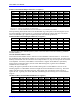
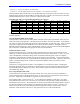
Ixx02 instructs Turbo PMAC where to place its output commands for Motor xx by specifying the address.
The default values of Ixx02 for Turbo PMACs with on-board PMAC2-style Servo ICs use the PWM
registers A, B, and C for the machine interface channel usually assigned to the motor. (PMAC-style
Servo ICs cannot be used for direct-PWM control.) Ixx02 seldom needs to be changed from the default
value for PWM applications. The actual address specified is that of the PWM A register; Turbo PMAC
then writes to the B and C registers automatically as well. Typically, the values used are: