
User's Manual


Turbo PMAC User Manual
118 Setting Up Turbo PMAC-Based Commutation and/or Current Loop
Note:
Generally, this test is not appropriate for linear motors, because of the relatively
uncontrolled movement it produces. It should only be done on unloaded rotary
motors. On linear motors, a fine phasing test can be done by adjusting the phase
position register so that no movement occurs when a large value of Ixx77 (e.g.
16,000) is given with an O0 command. The test should start with small values, and
movement quickly stopped with a K command.
Preparation
In the Detailed Plot menu of the data gathering section of the PMAC Executive program, set up to gather
the Direct Integrator Output and Quadrature Integrator Output registers. The gathering period should be
set to about 10 servo cycles. The addresses of the registers for each of the motors is:
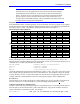
Direct Integrator Output Registers
Motor # 1 2 3 4 5 6 7 8
Address Y:$00BC Y:$013C Y:$01BC Y:$023C Y:$02BC Y:$033C Y:$03BC Y:$043C
Motor # 9 10 11 12 13 14 15 16
Address Y:$04BC Y:$053C Y:$05BC Y:$063C Y:$06BC Y:$073C Y:$07BC Y:$083C
Motor # 17 18 19 20 21 22 23 24
Address Y:$08BC Y:$093C Y:$09BC Y:$0A3C Y:$0ABC Y:$0B3C Y:$0BBC Y:$0C3C
Motor # 25 26 27 28 29 30 31 32
Address Y:$0CBC Y:$0D3C Y:$0DBC Y:$0E3C Y:$0EBC Y:$0F3C Y:$0FBC Y:$103C
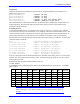
Quadrature Integrator Output Registers
Motor # 1 2 3 4 5 6 7 8
Address X:$00BC X:$013C X:$01BC X:$023C X:$02BC X:$033C X:$03BC X:$043C
Motor # 9 10 11 12 13 14 15 16
Address X:$04BC X:$053C X:$05BC X:$063C X:$06BC X:$073C X:$07BC X:$083C
Motor # 17 18 19 20 21 22 23 24
Address X:$08BC X:$093C X:$09BC X:$0A3C X:$0ABC X:$0B3C X:$0BBC X:$0C3C
Motor # 25 26 27 28 29 30 31 32
Address X:$0CBC X:$0D3C X:$0DBC X:$0E3C X:$0EBC X:$0F3C X:$0FBC X:$103C
Executing the Test
Before performing this test, first use the stepper-motor method of phasing to get close. Then, in the
terminal window of the Data Gathering section of the PMAC Executive, you can use the following set of
commands (wait a couple of seconds between commands):
DEFINE GATHER ; Reserve memory for gathered data
GAT O10 ; Positive command
O-10 ; Negative command
ENDG K ; Stop gathering and kill motor
Upload the gathered data and plot direct and quadrature voltage vs. time. The goal is to have the average
direct voltage reading be the same for the moves in both directions. The quadrature voltage will change
in sign at the move reversal. To adjust the system, wait until the motor is stopped after the test (M171 is
constant) and make a small adjustment to the M171 phase position register with a command like:
M171=M171+5
Then repeat the test as needed until the direct voltage readings are as close as possible in both directions.
This test is sensitive to a count of phasing error, so the last change should probably be +
1 count.
Using the Test Results for Absolute Sensor
This test is useful only when matching the super-accurate phase position to an absolute position sensor or
the index pulse of an incremental sensor. With an absolute sensor, assign an M-variable to the sensor
register, and add this to the Watch window. For example:
M175->TWR:0,0 ; Abs. pos. of 1st resolver on 1st Acc-8D Opt 7 R/D