
User's Manual


Turbo PMAC User Manual
214 Making your Application Safe
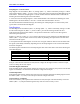
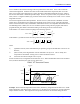
The following table shows the resistor pack for each channel for Turbo PMACs and accessories with this
feature. To enable the encoder-loss feature, pin 1 of the resistor pack (marked by a dot on the package)
should be placed at the opposite end of the socket from pin 1 of the socket (marked by a white-ink square
on the circuit board). For the 4-channel accessories (Acc-24E2x and 24C2x), the first four channels
shown are for accessories addressed as an even-numbered Servo IC (2, 4, 6, or 8); the second four
channels shown are for accessories addressed as an odd-numbered Servo IC (3, 5, 7, or 9).
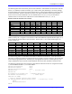
Resistor Packs for Encoder Loss Circuitry
Device Ch. 1 Ch. 2 Ch. 3 Ch. 4 Ch. 5/1 Ch. 6/2 Ch. 7/3 Ch. 8/4
PMAC-PCI RP60 RP62 RP66 RP68 RP97 RP99 RP103 RP105
PMAC2-PCI RP43 RP48 RP44 RP49 RP104 RP109 RP105 RP110
QMAC RP55 RP57 RP66 RP68 - - - -
Acc-24P2 RP74 RP75 RP85 RP86 RP139 RP140 RP150 RP151
Acc-24E2 RP22 RP24 RP22* RP24* RP22 RP24 RP22* RP24*
Acc-24E2A RP22 RP24 RP22* RP24* RP22 RP24 RP22* RP24*
Acc-24E2S RP19 RP21 RP27 RP29 RP19 RP21 RP27 RP29
Acc-24C2A RP33 RP34 RP63 RP64 RP33 RP34 RP63 RP64
* On the daughter board for the accessory module
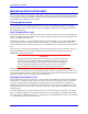
The following table shows the address of the encoder-loss status bit for each channel of each device. The
address is always for a Y-register. The x shown in some of the addresses represents the hex digit 8, 9, A,
or B, the same as the base address of the card itself. The bit value is 1 for a valid encoder signal; 0 to
signify encoder loss.
Device Ch. 1 Ch. 2 Ch. 3 Ch. 4 Ch. 5/1 Ch. 6/2 Ch. 7/3 Ch. 8/4
PMAC-PCI $70801,1 $70801,2 $70801,3 $70801,4 $70801,5 $70801,6 $70801,6 $70801,7
PMAC2-PCI $78403,8 $78403,9 $78403,10 $78403,11 $78403,8 $78403,9 $78403,10 $78403,11
QMAC $78403,8 $78403,9 $78403,10 $78403,11 - - - -
Acc-24P2 $7xF00,0 $7xF00,1 $7xF00,2 $7xF00,3 $7xF00,4 $7xF00,5 $7xF00,6 $7xF00,7
Acc-24E2 $7xF08,5 $7xF09,5 $7xF0A,5 $7xF0B,5 $7xF0C,5 $7xF0D,5 $7xF0E,5 $7xF0F,5
Acc-24E2A $7xF08,5 $7xF09,5 $7xF0A,5 $7xF0B,5 $7xF0C,5 $7xF0D,5 $7xF0E,5 $7xF0F,5
Acc-24E2S $7xF08,5 $7xF09,5 $7xF0A,5 $7xF0B,5 $7xF0C,5 $7xF0D,5 $7xF0E,5 $7xF0F,5
Acc-24C2A $7xF08,5 $7xF09,5 $7xF0A,5 $7xF0B,5 $7xF0C,5 $7xF0D,5 $7xF0E,5 $7xF0F,5
As of this writing, there is no automatic action taken on detection of encoder loss. Users who want to
take action on detecting encoder loss should write a PLC program to look for a change in the encoder loss
bit and take the appropriate action. Generally, the only appropriate response is to kill (open loop, zero
output, disabled) the motor with lost encoder feedback; other motors may be killed or aborted as well.
The following example shows how all motors can be killed on detection of the loss of signal for Encoder
1, used as feedback for Motor 1, on a Turbo PMAC.
#define Mtr1OpenLoop M138
#define Enc1LossIn M180
#define Mtr1EncLossStatus P180
#define Lost 0 ; Low-true fault
#define OK 1
Mtr1OpenLoop->Y:$0000B0,18,1 ; Standard definition
Enc1LossIn->Y:$078403,8,1 ; CTRL0 input
OPEN PLC 18 CLEAR
; Logic to disable and set fault status
IF (Mtr1OpenLoop=0 AND Enc1LossIn=Lost) ; Closed loop, no enc
CMD^K
Mtr1EncLossStatus=1
ENDIF