
User's Manual


Turbo PMAC User Manual
Setting Up Feedback and Master Position Sensors 67
≅≅
≅≅
=
inch
increments
1060
increment
inches
00094.0
sec
inches
0.9
1
*
increment
sec
96.117
1
mm
increments
3.41
increment
mm
024.0
sec
mm
35.0
1
*
increment
sec
96.117
1
sec
length
turnSpeedRe*
increment
sec
TimerFreq
1
increment
length
solutionRe
µ
µ
µ
µ
µ
µ
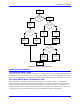
Axis User Units
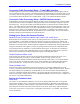
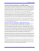
Typically the axis assigned to the motor using the MLDT for feedback will be given engineering units of
millimeters or inches. The scaling is done in the axis definition statement. With the above example, an
axis definition statement to create axis user units of millimeters would be:
#1->41.3X
An axis definition statement to create axis user units of inches would be:
#1->1060X
Setting Up LVDTs, RVDTs, & Other Analog
Turbo PMAC systems can accept analog voltages from devices such as linear variable displacement
transducers (LVDTs), rotary variable displacement transducers (RVDTs), capacitive gauges, and
potentiometers, as feedback through optional analog-to-digital converters. These voltages must be DC;
that is, a constant position must be represented by a constant DC voltage (not an AC magnitude). This
means if the sensor is fundamentally AC with a carrier frequency (e.g. LVDTs, RVDTs), the sensor signal
must be demodulated to remove the AC carrier signal before it is connected to the Turbo PMAC system.
Typically, the vendors of these sensors can provide this kind of signal conditioning.
Hardware Setup
The analog signal should be wired into the connector for the analog accessory or option according to the
directions in the associated manual. If there is provision for differential inputs, and a single-ended input
is being used, physically wire the complementary input to the return voltage to get a proper reading
through the differential receiver.
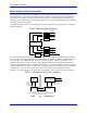
Turbo PMAC Hardware-Control Parameter Setup
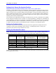
Most of the 12-bit A/D converters – as on Acc-36P, Acc-36V, Acc-36E, Acc-6E, and Option 12 – use
multiplexed converters. The first step in accessing these for servo use is to de-multiplex the data at a
fixed high rate. In Turbo PMAC, this de-multiplexing step is controlled by variables I5060 – I5096.
Each phase interrupt, one pair of ADCs is read and copied into memory registers and the next pair is
selected for the next conversion. Up to 16 pairs of ADCs can be in this ring. The de-multiplexed data is
left in registers Y:$003400 – Y:$00341F, where it can be read by the conversion table.
If the 12-bit A/D converters are in the MACRO Station, this de-multiplexing process is controlled by
Station variables MI987 and MI989. It is a fixed de-multiplexing of eight pairs of ADCs from one
device. MI989 specifies the address of the ADCs, and MI987 is set to 1 to enable the process. The
resulting data is placed in Station registers Y:$0200 – Y:$0207, with each pair of 12-bit values in a 24-bit
register.