
User's Manual

Turbo PMAC User Manual
Basic Motor Setup 75
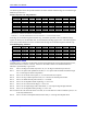
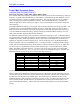
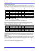
The following table shows the possible addresses for these variables when the flags are accessed through
PMAC2-style Servo ICs.
PMAC2-Style Servo IC Flag Addresses
IC# - Chan# 0 - 1 0 - 2 0 - 3 0 - 4 1 - 1 1 - 2 1 - 3 1 - 4
Ixx25/42/43
$078000 $078008 $078010 $078018 $078100 $078108 $078110 $078118
IC# - Chan# 2 - 1 2 - 2 2 - 3 2 - 4 3 - 1 3 - 2 3 - 3 3 - 4
Ixx25/42/43
$078200 $078208 $078210 $078218 $078300 $078308 $078310 $078318
IC# - Chan# 4 - 1 4 - 2 4 - 3 4 - 4 5 - 1 5 - 2 5 - 3 5 - 4
Ixx25/42/43
$079200 $079208 $079210 $079218 $079300 $079308 $079310 $079318
IC# - Chan# 6 - 1 6 - 2 6 - 3 6 - 4 7 - 1 7 - 2 7 - 3 7 - 4
Ixx25/42/43
$07A200 $07A208 $07A210 $07A218 $07A300 $07A308 $07A310 $07A318
IC# - Chan# 8 - 1 8 - 2 8 - 3 8 - 4 9 - 1 9 - 2 9 - 3 9 - 4
Ixx25/42/43
$07B200 $07B208 $07B210 $07B218 $07B300 $07B308 $07B310 $07B318
Servo ICs 0 and 1 are on the Turbo PMAC2 itself or on Acc-2E 3U-format stack boards.
Servo ICs 2 – 9 are on Acc-24x2 or Acc-51E boards.
Channels 1 – 4 on odd-numbered Servo ICs are Channels 5 – 8 on the dual-IC boards.
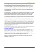
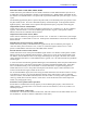
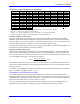
If the flags are accessed through the MACRO ring, the address specified is that of a dedicated image
register in memory for the MACRO node, not the MACRO node flag register itself. The following table
shows the possible addresses for these variables when the flags are accessed through the MACRO ring.
MACRO Ring Flag Addresses
IC# - Node# 0 - 0 0 - 1 0 - 4 0 - 5 0 - 8 0 - 9 0 - 12 0 - 13
Ixx25/42/43
$003440 $003441 $003444 $003445 $003448 $003449 $00344C $00344D
IC# - Node# 1 - 0 1 - 1 1 - 4 1 - 5 1 - 8 1 - 9 1 - 12 1 - 13
Ixx25/42/43
$003450 $003451 $003454 $003455 $003458 $003459 $00345C $00345D
IC# - Node# 2 - 0 2 - 1 2 - 4 2 - 5 2 - 8 2 - 9 2 - 12 2 - 13
Ixx25/42/43
$003460 $003461 $003464 $003465 $003468 $003469 $00346C $00346D
IC# - Node# 3 - 0 3 - 1 3 - 4 3 - 5 3 - 8 3 - 9 3 - 12 3 - 13
Ixx25/42/43
$003470 $003471 $003474 $003475 $003478 $003479 $00344C $00347D
Flag Modes: Ixx24
Variable Ixx24 is a collection of individual control bits that determines how the flags specified in Ixx25,
Ixx42, and Ixx43 are used (or not used). Each bit is described in detail in the Software Reference
Manual; a quick summary is given here.
Bit 0: Set to 0 for flags in a PMAC-style Servo IC, to 1 for flags in a PMAC2-style Servo IC.
Bit 11: Set to 0 to capture with quadrature encoders, to 1 to capture with sinusoidal encoders through
Acc-51 with high-resolution interpolation.
Bit 12: Set to 0 to use whole-count capture, to 1 to use fractional-count capture.
Bit 14: Set to 0 to stop on desired-position limit, to 1 to saturate on desired-position limit.
Bit 15: Set to 0 to disable desired-position limits, to 1 to enable.
Bit 16: Set to 0 to use amplifier-enable output flag, to 1 not to use.
Bit 17: Set to 0 to use overtravel limit flags, to 1 not to use.
Bit 18: Set to 0 to use capture flags from Turbo PMAC, to 1 for capture flags through MACRO.
Bit 20: Set to 0 to use amplifier-fault input flag, to 1 not to use.
Bits 21 and 22: Set to 00 to kill all motors on a fault; to 01 to kill motors in same coordinate system, to 10
to kill only faulted motor.
Bit 23: Set to 0 for low-true amplifier fault (0 means fault), to 1 for high-true amplifier fault.