(Model 14-650) PART NO. 900651 (011) Copyright © 2001 Delta Machinery To learn more about DELTA MACHINERY visit our website at: www.deltamachinery.com. For Parts, Service, Warranty or other Assistance, please call ESPAÑOL: PÁGINA 19 1-800-223-7278 (In Canada call 1-800-463-3582).
SAFETY RULES Woodworking can be dangerous if safe and proper operating procedures are not followed. As with all machinery, there are certain hazards involved with the operation of the product. Using the machine with respect and caution will considerably lessen the possibility of personal injury. However, if normal safety precautions are overlooked or ignored, personal injury to the operator may result.
ADDITIONAL SAFETY RULES FOR HOLLOW CHISEL MORTISERS 1. DO NOT operate your mortiser until it is completely assembled and installed according to the instructions. 15. SHUT-OFF the power, remove the drill bit and chisel, and clean the table before leaving the machine. 2. IF YOU ARE NOT thoroughly familiar with the operation of mortisers, obtain advice from your supervisor, instructor, or other qualified person. 16. FOR YOUR OWN SAFETY – Don’t wear gloves when operating the machine. 4.
UNPACKING AND CLEANING Carefully unpack the mortiser and all loose items from the carton. Remove the protective coating from the machined surfaces of the mortiser. This coating may be removed with a soft cloth moistened with kerosene. Do not use acetone, gasoline, or lacquer thinner for this purpose. Fig. 2 illustrates the mortiser and all loose items removed from the carton. A O N M P G B H R J F D H L E G C K Fig.
ASSEMBLY INSTRUCTIONS WARNING: FOR YOUR OWN SAFETY, DO NOT CONNECT THE MACHINE TO THE POWER SOURCE UNTIL THE MACHINE IS COMPLETELY ASSEMBLED AND YOU HAVE READ AND UNDERSTOOD THE ENTIRE OWNER’S MANUAL. ASSEMBLING RAISING AND LOWERING HANDLE B 1. Assemble hub of handle assembly (A) Fig. 3, to end of pinion shaft (B) and fasten handle to pinion shaft using special screw (C) and spring (D). A D C Fig. 3 2. Raise mortising machine head (E) Fig. 4, to the up position by turning handle (A) clockwise.
2. Fig. 6, illustrates the hydraulic cylinder (B) assembled to the machine. The hydraulic cylinder (B) keeps the head in the up position. B Fig. 6 ASSEMBLING TABLE 1. Assemble the table (A) Fig. 7, to the base using the two M6 x 35mm flat head screws (B) and T-nuts (C). Insert the two screws (B) into the two holes (D) in table board (A). Place the two T-nuts (C) into the slots provided in the bottom of the base and tighten the two screws (B) into the two T-nuts (C) securely. B 2. The table (A) Fig.
2. Thread stud (D) Fig. 9, into hole on side of column, as shown. Do not thread stud (D) all the way into hole at this time. D 3. Reassemble handle (C) Fig. 9, on stud (D) and replace screw (A) and spring (B). B C A Fig. 9 4. Fig. 10 illustrates the handle assembly (C) assembled to the column. C Fig. 10 5. Insert bar of fence assembly (E) Fig. 11, through hole in column as shown. Tighten handle (C) against flat on fence bar to hold fence in position.
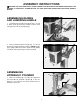
7. Assemble the holddown (H) Fig. 13, onto bar (F) as shown, and tighten set screw (J) against flat on bar. H J F Fig. 13 ASSEMBLING TOOL AND CHISEL HOLDER 1. Assemble tool and chisel holder (A) Fig. 14, to side of column using the two M6 x 25mm screws (B) and flat washers as shown. B A Fig. 14 2. Fig. 15, illustrates the chuck key (C), wrench (D) and chisels and bits (E) in holes of tool and chisel holder (A) when not in use. E D C A Fig.
CONNECTING MORTISER TO POWER SOURCE POWER CONNECTIONS A separate electrical circuit should be used for your tools. This circuit should not be less than #12 wire and should be protected with a 20 Amp time lag fuse. If an extension cord is used, use only 3-wire extension cords which have 3prong grounding type plugs and 3-pole receptacles which accept the tool’s plug.
EXTENSION CORDS MINIMUM GAUGE EXTENSION CORD RECOMMENDED SIZES FOR USE WITH STATIONARY ELECTRIC TOOLS Use proper extension cords. Make sure your extension cord is in good condition and is a 3-wire extension cord which has a 3-prong grounding type plug and a 3-hole receptacle which will accept the tool’s plug. When using an extension cord, be sure to use one heavy enough to carry the current of the machine. An undersized cord will cause a drop in line voltage resulting in loss of power and overheating.
4. Push bit (A) Fig. 23, up through chisel and into chuck (G) as far as it will go, and then back the bit off 1/16", and lock bit in chuck using chuck key supplied. G A Fig. 23 5. Loosen set screw (D) Fig. 24, and push chisel (B) up against bottom of bushing (E), as shown, and tighten set screw (D). This should provide the proper distance between the cutting lips of the bit and the points of the chisel. D E B Fig. 24 6.
OPERATING CONTROLS AND ADJUSTMENTS SWITCH The switch (A) Fig. 26, is located on the side of the motor. To start the mortiser, move the switch (A) to the up position. To turn the mortiser “OFF” move the switch to the down position A Fig. 26 LOCKING SWITCH IN THE “OFF” POSITION When the tool is not in use, the switch be locked in the “OFF” position to prevent unauthorized use. This can be done by grasping the switch toggle (B) Fig. 27, and pulling it out of the switch, as shown.
ADJUSTING DEPTH STOP ROD C A depth stop rod (A) Fig. 29, is provided to limit the depth of the chisel (B). To adjust the depth stop rod (A), loosen screw (C) and lower head until the chisel (B) is at the desired depth. Lower depth stop rod (A) until it contacts base (D) and tighten screw (C). A B D Fig. 29 ADJUSTING FENCE The fence (A) Fig. 30, can be moved in or out by loosening lever (B), sliding fence to the desired position and tightening lever (B).
ADJUSTING SLIDING FIT BETWEEN HEAD AND COLUMN B A dovetail gib (A) Fig. 32, is provided on the rear of the head to insure a good sliding fit between the head and the column when the head is raised and lowered. Adjustment is made by loosening the two screws (B) and turning adjusting screws (C). Then tighten two screws (B). NOTE: Correct adjustment is when a good snug sliding fit is obtained without any side movement between the gib and the column.
USING AUXILIARY WOOD FENCE When mortising extra high workpieces (A) Fig. 35, an auxiliary fence (B) can be fastened to the fence (C) with wood screws (D) through the two holes in the fence. This provides additional support for the workpiece during the mortising operation. Note that the holddown (E) can be turned upside down to accommodate the extra height of the workpiece. E A B D C Fig. 35 ROTATING COLUMN 180 DEGREES The column (A) Fig.
USING BITS WITH EXTRA LONG SHANKS A C When using bits with extra long shanks, it will be necessary to remove the extension (A) Fig. 37. This can be accomplished by inserting screwdriver into center hole of motor end cap (B) Fig. 38, and into slot in end of armature shaft. Then using chuck key, unscrew and remove chuck (C) Fig. 37, and extension (A). Remove extension (A) from chuck (C) and replace chuck (C) on end of motor shaft. Fig. 37 B Fig.
NOTES 17
PARTS, SERVICE OR WARRANTY ASSISTANCE All Delta Machines and accessories are manufactured to high quality standards and are serviced by a network of PorterCable•Delta Factory Service Centers and Delta Authorized Service Stations. To obtain additional information regarding your Delta quality product or to obtain parts, service, warranty assistance, or the location of the nearest service outlet, please call 1-800-223-7278, (In Canada call 1-800-463-3582).