(Model 14-651) PART NO. 910209 - 04-28-04 Copyright © 2004 Delta Machinery To learn more about DELTA MACHINERY visit our website at: www.deltamachinery.com. ESPAÑOL: PÁGINA 15 For Parts, Service, Warranty or other Assistance, please call 1-800-223-7278 (In Canada call 1-800-463-3582).
SAFETY GUIDELINES - DEFINITIONS This manual contains information that is important for you to know and understand. This information relates to protecting YOUR SAFETY and PREVENTING EQUIPMENT PROBLEMS. To help you recognize this information, we use the symbols below. Please read the manual and pay attention to these sections. Indicates an imminently hazardous situation which, if not avoided, will result in death or serious injury.
GENERAL SAFETY RULES FAILURE TO FOLLOW THESE RULES MAY RESULT IN SERIOUS INJURY. 12. USE THE RIGHT MACHINE. Don’t force a machine or an attachment to do a job for which it was not designed. Damage to the machine and/or injury may result. 13. USE RECOMMENDED ACCESSORIES. The use of accessories and attachments not recommended by Delta may cause damage to the machine or injury to the user. 14. USE THE PROPER EXTENSION CORD. Make sure your extension cord is in good condition.
ADDITIONAL SAFETY RULES FOR HOLLOW CHISEL MORTISERS FAILURE TO FOLLOW THESE RULES MAY RESULT IN SERIOUS INJURY. 1. 2. 3. 4. 5. 6. 7. 8. 9. 10. 11. 12. DO NOT OPERATE THIS MACHINE until it is completely assembled and installed according to the instructions. A machine incorrectly assembled can cause serious injury. OBTAIN ADVICE from your supervisor, instructor, or another qualified person if you are not thoroughly familiar with the operation of this machine. Knowledge is safety.
POWER CONNECTIONS A separate electrical circuit should be used for your machines. This circuit should not be less than #12 wire and should be protected with a 20 Amp time lag fuse. If an extension cord is used, use only 3-wire extension cords which have 3prong grounding type plugs and matching receptacle which will accept the machine’s plug.
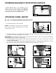
EXTENSION CORDS Use proper extension cords. Make sure your extension cord is in good condition and is a 3-wire extension cord which has a 3-prong grounding type plug and matching receptacle which will accept the machine’s plug. When using an extension cord, be sure to use one heavy enough to carry the current of the machine. An undersized cord will cause a drop in line voltage, resulting in loss of power and overheating. Fig. D-1 or D-2, shows the correct gauge to use depending on the cord length.
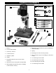
CARTON CONTENTS 8 1 11 9 12 10 13 14 15 16 17 5 2 6 7 3 4 Fig. 2 1. Mortiser 10. M6x1x25mm Pan Head Screws (2) (for assembling tool and chisel holder) 2. Tool and Chisel Holder 11. Spring 3. Chuck Key / Wrench 12. Bushing (for use with extra long chisels) 4. Column Extension 5. Hydraulic Cylinder 13. M6 Lockwashers (2) (for assembling tool and chisel holder) 6. Handle 14. 1/2" Mortising Chisel and Bit 7. Extended hold-down rod (use with column extension) 15.
ASSEMBLY For your own safety, do not connect the machine to the power source until the machine is completely assembled and you read and understand the entire instruction manual. RAISING AND LOWERING HANDLE 1. Attach the hub of the handle assembly (A) Fig. 3 to the end of the pinion shaft (B) and fasten the handle to the pinion shaft using the special screw (C) and spring (D). 2. Raise the mortising machine head (E) Fig. 4 to the "up" position by turning the handle (A) clockwise.
FASTENING MACHINE TO SUPPORTING SURFACE If during operation there is any tendency for the mortiser to tip over, slide or walk on the supporting surface, the base must be secured to the supporting surface with fasteners (not supplied), through the two holes (A) Fig. 9, located in the mortiser base. A Fig. 9 ATTACHING CHISEL AND BIT DISCONNECT MACHINE FROM POWER SOURCE. 1. Insert the bit (A) Fig. 10 in the chisel (B).
PUSH THE CHISEL AGAINST THE BUSHING 5. Adjust the flat portion of the bit to a minimum of 1/16" below the bottom of the chisel. Certain types of wood may require an increase in this gap up to a maximum of 3/16". ADJUST THE BIT IN THE CHUCK TO GIVE CLEARANCE ATTACHING COLUMN EXTENSION 1/16" to 3/16" CLEARANCE DEPENDING ON THE TYPE OF WOOD The column can be extended for the purpose of mortising taller work pieces. To extend the column: Fig. 15 DISCONNECT MACHINE FROM POWER SOURCE. 1. 2. 3. 4. 5. 6. 7.
NOTE: Reverse the procedure to remove the column extension. A To prevent damage to the unit, place the rack cover over the gear. This action will prevent the cover from being trapped between the rack and the gear. B C Fig. 20 OPERATING CONTROLS AND ADJUSTMENTS STARTING AND STOPPING MORTISER The power switch is located on the left side of the mortiser. To turn the mortiser “ON”, press the green start button (A) Fig. 21. To stop the mortiser, push the red button (B). A B Fig.
HOLD-DOWN C The hold-down (C) Fig. 25 prevents the workpiece (E) from lifting as the chisel is lifted out of the hole. To adjust the hold-down, loosen the handle (F), position the holddown so that it just touches the top of the workpiece (E), then tighten the handle. You can turn the hold-down (C) upside down to accommodate thicker workpieces. E F Fig. 25 CHISEL PARALLEL TO WORKPIECE The chisel (A) Fig.
ROTATING COLUMN 180 DEGREES The column (A) Fig. 29 can be rotated 180 degrees for special cuts off of the table. To rotate the column, remove four screws, two of which are shown at (B), rotate the column (A) 180 degrees, and replace the four screws (B). The base must be secured to a supporting surface. USING BITS WITH EXTRA LONG SHANKS When using bits with extra long shanks, remove the extension (A) Fig. 30.
ACCESSORIES A complete line of accessories is available from your Delta Supplier, Porter-Cable • Delta Factory Service Centers, and Delta Authorized Service Stations. Please visit our Web Site www.deltamachinery.com for a catalog or for the name of your nearest supplier. Since accessories other than those offered by Delta have not been tested with this product, use of such accessories could be hazardous. For safest operation, only Delta recommended accessories should be used with this product.
PORTER-CABLE • DELTA SERVICE CENTERS (CENTROS DE SERVICIO DE PORTER-CABLE • DELTA) Parts and Repair Service for Porter-Cable • Delta Machinery are Available at These Locations (Obtenga Refaccion de Partes o Servicio para su Herramienta en los Siguientes Centros de Porter-Cable • Delta) ARIZONA Tempe 85282 (Phoenix) 2400 West Southern Avenue Suite 105 Phone: (602) 437-1200 Fax: (602) 437-2200 CALIFORNIA Ontario 91761 (Los Angeles) 3949A East Guasti Road Phone: (909) 390-5555 Fax: (909) 390-5554 Tampa 3360