
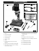
Instruction manual


9
If during operation there is any tendency for the
mortiser to tip over, slide or walk on the supporting
surface, the base must be secured to the supporting
surface with fasteners (not supplied), through the two
holes (A) Fig. 9, located in the mortiser base.
1. Insert the bit (A) Fig. 10 in the chisel (B).
NOTE: The opening (C) on the side of the chisel (that
allows chips to escape) should always face the side,
never the front or rear.
FASTENING MACHINE TO SUPPORTING SURFACE
A
ATTACHING CHISEL AND BIT
DISCONNECT MACHINE FROM POWER SOURCE.
A
B
C
Fig. 9
Fig. 10
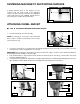
2. Loosen the screw (D) Fig. 11, and push the chisel (B) up through the hole in the head as far as possible. Lower the
chisel (B) 1/16" to 3/16" and tighten the set screw (D).
IMPORTANT: When inserting the chisel (B) Fig. 12 into the head, leave a space of 1/16" to 3/16" clearance (F) between
the bushing (E) and the shoulder of the chisel (B).
3. Push the bit (A) Fig. 13 up through the chisel and into the chuck (G) as far as it will go. Lock the bit in the chuck
using the supplied chuck key.
4. Loosen the set screw (D) Fig. 14, and push the chisel (B) against the bottom of the bushing (E), and tighten the set screw
(D) to provide the proper distance between the cutting lips of the bit and the points of the chisel.
Fig. 11
Fig. 12
D
B
D
E
F
B
G
A
Fig. 13
D
E
B
Fig. 14