Installation & Maintenance Instructions Model 140 Delta Meter & Model 140 Electrical Reading Office Aberdeen Office Cutbush Park, Danehill, Lower Earley, Reading, Berkshire. RG6 4UT. UK. Tel: +44 (0)118 9311188 Email: info@able.co.uk Unit 6 Airside Business Park, Kirkhill Industrial Estate, Dyce, Aberdeen. AB21 0GT. UK. Tel: +44 (0)1224 725999 Email: ab@able.co.uk Internet: www.able.co.uk e-procurement: www.247able.
BULLETIN NO. IM140-02 Mid-West (Supersedes BULLETIN NO. IM140/01) ® Instrument Model 140 "DELTA METER Installation and Operating Instructions INSPECTION Before installation check the nameplate on each instrument against the receiving paperwork and the intended application for correct part number, materials of construction, working pressure, dial range, etc. If equipped with switches, check electrical rating, type of enclosure, etc. Inspect for shipping damage and, if damaged, report it immediately.
Be sure these get plumbed to the proper connections on your system. Improper connection will not damage the instrument, but it will not function properly. Flexible tubing is recommended to minimize effect of any vibration that may exist. 2. INSTRUMENT LOCATION On liquid service, the instrument should be mounted below the process connections to facilitate self-bleeding. On gas service, it should be located above the process connections to promote self-draining.
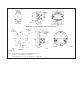
MODEL 140 - 2-1/2 INCH PLASTIC DIAL ASSY. (STANDARD) MODEL 140 - 4-1/2 PLASTIC INCH DIAL ASSY. (OPTIONAL) (Fig. 5) NOTES: 1. Drawings show standard gauge nominal dimensions. (not to scale) 2. Dimensions shown in parentheses are in millimeters. 3. Mounting Dimensions for 3-1/2" & 4-1/2" Alum. Dial Assys. – Contact Factory Manufacturer reserves the right to change specifications without prior notice. All dimensions in inches and millimeters.
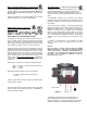
BULLETIN NO. ELEC-IM140/11A Replaces ELEC-IM140-141/09A Mid-West ® Instrument Model 140 Electrical Installation and Operating Instructions ELECTRICAL Gauges with switches have one or two SPST or SPDT hermetically sealed adjustable set point reed switch assemblies. Resistive load ratings and capabilities for each reed switch type are defined as follows: * Type *Power Max. Current Max. Voltage Setting (F.S.) Hysterisis (Max/Nom) SPST(Norm Open) 25 W 0.5 Amps 240 VAC/VDC 15% to 90% 15% / 8% Full Scale(F.
Division II Hazardous Ratings (E ,F, & W) options): Transmitter Option: (T & W ) Electrical Configuration) rd The E, F, & W Electrical Configurations are 3 party certified to both Canadian and U.S. standards for Class I, Division II, Groups A, B, C, & D, Class II, Groups F & G hazardous environments The Model 140/141 Transmitter is intended for use in General Purpose Locations (T electrical configuration) or Division 2 locations (W electrical configuration).
Connect loop power between the connections labeled 8-28 Vdc and RTN. Connect the protective conductor wire to the terminal with the symbol. A zero pushbutton is also included. Zero the transmitter with the transmitter powered and no differential pressure applied by depressing the switch for a minimum of 2 seconds. The maximum loop resistance is 1000 ohms (@ 28Vdc Input).
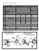
TRANSMITTER SPECIFICATIONS: Transmitter Specifications: (Calibrated on Increasing pressure) Differential Pressure Range 0-50” H2O to 0 -100 PSID Leakage None Hi to Lo Comments: Pressure (Ratings) Max Working See Specifications ASME B40.100 GRADE B Gauge Accuracy 2% Operating Temperature (Max.
Electrical Configuration: A or B NEMA 4X 2 ½ INCH DIAL Electrical Configuration: E or F NEMA 4X METAL ENCLOSURE Class I, Div. 2, Groups A, B, C,D Class II, Div 2, Groups F & G Electrical Configuration: A or B NEMA 4X 4 ½ INCH DIAL Electrical Configuration: C or D Explosion-Proof Enclosures Class I, Groups C & D Class II, Groups E, F, & G Dial Size DIM 2½ 2½ 4½ A 7.12 (180.9) 6.53 (163.3) 8.50 (215.9) B 4.15 (105.4) 2.12 (53.84) 2.50 (62.5) C 3.15 (80.01) 3.12 (79.24) 4.35 (110.5) D 6.
BULLETIN NO. ELEC-IM140/11A Replaces ELEC-IM140-141/09A Mid-West ® Instrument CE Marking Statements: The Electrical Configurations A,B, E, & F of this product are CE marked in compliance with the Low Voltage Directive to EN-61010-1. These products shall not be placed in an Explosive atmosphere as defined by the ATEX Directive 94/9/EC except if evaluated to be “Simple Apparatus”. They may be classified as simple apparatus.