
Operating instructions


BULLETIN NO. IM140-02
(Supersedes BULLETIN NO. IM140/01)
Mid-West
®
Instrument
INSPECTION
Before installation check the nameplate on
each instrument against the receiving
paperwork and the intended application for
correct part number, materials of construction,
working pressure, dial range, etc. If equipped
with switches, check electrical rating, type of
enclosure, etc. Inspect for shipping damage
and, if damaged, report it immediately.
NOTE - Before attempting repairs contact
your local Mid-West Representative
or our factory. Failure to do so will
void any warranty.
PR
ODUCT DESCRIPTION
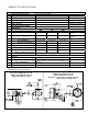
The Model 140/141 “Series” is a medium range
differential pressure instrument available as a
switch, a gauge, or both. See “Part Numbering
System”, (Fig. 6) for available options.
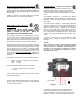
A flexible elastomer diaphragm and calibrated
range spring are moved by differential
pressure. A pair of magnets, coupled with the
diaphragm, transmit this motion through the
wall of the pressure housing to a follower
magnet attached to an indicating pointer. The
rotation of the follower magnet causes the
pointer to track movement of internal magnet
and indicate the differential on the dial scale.
When equipped with switches, a contact is
made, or broken, by the magnetic field of the
internal magnets.
The diaphragm is totally supported upon
reaching full travel in either direction, providing
full over-range protection to the rated working
pressure of the housing.
INST
ALLA
TION
Model 140/141 “Series” is calibrated and tested
prior to shipment and is ready for immediate
installation. Use of the following installation
procedures should eliminate potential damage
and provide optimum trouble-free operation.
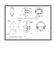
1. CONNECTIONS
1/4" FNPT is provided as standard but check
paperwork for connections ordered. There are
two connections on the housing identified as
“hi” and “lo” for high pressure and low pressure.
Model 140 "DELTA METER
Installation and Operating Instructions