
Operating instructions


BULLETIN NO. ELEC-IM140/11A
Replaces ELEC-IM140-141/09A
Instrument
Mid-West
®
ELECTRICAL
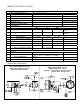
Gauges with switches have one or two SPST or SPDT
hermetically sealed adjustable set point reed switch
assemblies. Resistive load ratings and capabilities for each
reed switch type are defined as follows:
Type SPST(Norm Open) SPDT
*Power 25 W 3W
Max. Current 0.5 Amps 0.25 Amps
Max. Voltage 240 VAC/VDC 125 VAC/VDC
Setting (F.S.) 15% to 90% 15% to 90%
Hysterisis
(Max/Nom)
15% / 8%
Full Scale(F.S.)
10% / 5%
Full
Scale(F.S.)
Repeatability 1% F.S. 1% F.S.
* Product of the switching voltage and current shall
not exceed the power rating of the device.
Provide standard protection techniques for the switch
contacts for capacitive and inductive loads. Use current
limiting techniques near the switch to protect the contacts
due to high inrush (i.e.; in line resistor or inductor) for long
cable interfaces. Provide clamping devices at or near
inductive loads (i.e.; relay). Long cable runs can be
considered both inductive and capacitive, therefore also
clamp across the switch. We recommend for long cable
runs of 70 feet or greater that you use the SPST switch or
use a current limiting resistor wired in series and located near
the switch. Contact the factory if you need assistance.
Please note that the SPST switch is available in only the
Normally Open configuration
Both switch types are field adjustable from 15% to 90% of full
scale reading of the gauge.. All switches come with a decal
to identify adjustment direction to increase the set point. To
set the switch at a desired set point on increasing pressure
apply pressure to the gauge for the desired set point. Adjust
the switch so that it is adjusted above the set point (normally
open contacts are open) and slowly decrease the set point
until the switch activates (normally open contact closes).
Remove pressure and slowly reapply to determine the actual
setting. This process can be repeated to achieve a more
accurate setting.
All switch functionalities shown are with the gauge at 0 PSID.
The SPST switches are available in the Normally Open
configuration only.
Use the Mid-West Power Relay 1000TR or equivalent relay
for loads above the switch rating.
The following warnings apply to all gauge options with
electrical interface.
WARNING: ELECTRICAL CONNECTIONS SHOULD
BE PERFORMED BY QUALIFIED
PERSONNEL AND MEET THE
REPRESENTATIVE COUNTRY'S
NATIONAL ELECTRICAL CODE.
WARNING: FAILURE TO CONNECT TO THE
PROTECTIVE CONDUCTOR TERMINAL
MAY RESULT IN A SHOCK HAZARD.
WARNING: REMOVAL OR REPLACEMENT OF
INSTRUMENT HARDWARE VOIDS ALL
WARRANTIES AND CONFORMANCES TO
ANY STANDARDS (EXCEPT COVERS
AND OR SWITCH ADJUST PLUGS).
NEMA 4X (Plastic Weatherproof Enclosure)
(A & B options)
The reed switch(es) are located inside the enclosure, on the
top of the pressure housing, and are connected to a 7
position terminal strip. An opening is provided at the rear
of the enclosure for a 1/2" flexible weather-proof cable or
conduit connector (supplied by customer). Upon request the
hole may be sized to accommodate a PG-11 cable gland
connector.
Remove the switch enclosure cover by removing the (4)
screws. Insert wires through an appropriate (not supplied)
weatherproof connector into the enclosure and connect to
the terminal strip per the terminal strip diagram shown below
or on the underside of the switch enclosure cover. The
center connection is for connection of a protective conductor
and is connected to the body of the pressure gauge.
The terminal strip will accept wires in the range of 22 Awg -
16 Awg.. Reinstall the cover, gasket, and (4) screws. (Fig.
3) after connection of field wiring.
Wiring for the SPST switches is connected between NO and
CM connections on the terminal strip. Normally closed
switches are not available.
Access holes and plugs are provided for external adjustment
of the switches if required.
Gauge
Front
NO NC CM CM NC NO
SINGLE DOUBLE
Model 140 Electrical
Installat
ion and Operating Instructions