
Operating instructions


Division II Hazardous Ratings (E ,F, & W) options):
The E, F, & W Electrical Configurations are 3
rd
party certified
to both Canadian and U.S. standards for Class I, Division II,
Groups A, B, C, & D, Class II, Groups F & G hazardous
environments
Interface is identical to the plastic weatherproof enclosure
with the exception of a ½” FNPT conduit interface.
NEMA 7 (Explosion-proof ) Enclosure
(C & D options)
WARNING: THE COVER AND/OR SWITCH ADJUST
ACCESS PLUGS MUST NEVER BE REMOVED WHEN
THERE IS POWER TO THE UNIT. MAKE ALL
ADJUSTMENTS IN A NONHAZARDOUS AREA.
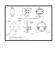
The gauge and switches are mounted inside the enclosure.
A 1/2"-14 FNPT conduit connection is provided in the bottom
side of the enclosure. A proper explosion proof, dust tight
sealing fitting with appropriate sealing cement must be used
when making connections to the 24", 18 Awg. wire leads.
Adjustment of the set point can be accomplished by removing
the switch adjustment access plug(s). Insert the screw driver
through the hole into the switch adjustment slot and rotate
until the desired set point is reached. A clockwise rotation
will increase the set point for the right side switch access
and a clockwise rotation will decrease the set point for left
switch access. Do not use excessive force
. Reinstall the
access plugs for 5 full threads of engagement after
completion.
SPDT Switch leads are color coded and labeled as follows:
White- 1 or 2 Com (1 Right Access 2 Left Access)
Black- 1 or 2 NC
Red - 1 or 2 NO
SPST Switch leads are black in color and are labeled:
1 or 2 Com (1 Right Access 2 Left Access)
1 or 2 NO
A green / yellow wire is provided for proper electrical bonding
of the enclosure chassis.
Enclosures with SPDT and SPST switches comply with NEC
Class 1, Groups C & D, Class 2 Groups E, F, & G, NEMA 7 &
9, and are CSA & UL listed.
Transmitter Option: (T & W ) Electrical Configuration)
The Model 140/141 Transmitter is intended for use in
General Purpose Locations (T electrical configuration) or
Division 2 locations (W electrical configuration). In both
cases the enclosure carries a NEMA 4X IP65 environmental
rating.
The transmitter assembly as a component has passed
numerous European EMC standards (ie; Compliance to IEC
EN61326). Contact the factory if additional low pass filtering
is necessary.
The Model 140/141 indicating / non-indicating differential
pressure transmitter is a 2 wire loop powered microprocessor
based 4-20 ma transmitter. The magnetic angle sensor &
electronics senses the angle (relative to the transmitter
sensor) of the magnet which moves linearly in the bore.
Each transmitter is individually calibrated to the gauge using
an 11 point calibration linearization technique. This method
results in a <2% full scale accuracy for the upper 80% of the
range.
In addition, an external zero pin is available for simple
remote zeroing (instead of supplied local zero) after
installation.
Caution:
Do not attempt to reposition the transmitter assembly
within the enclosure. This voids the warranty and will
“knock” the unit out of calibration. Disassembly and re-
assembly of any internal process parts will also require
the unit to be re-calibrated. Calibration must be
performed at the factory.
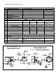
The weather-proof enclosure comes standard with a ½”
FNPT conduit interface. Internal to the enclosure is a 4
position terminal strip. The terminal strip accepts wire sizes
22 AWG – 16 AWG. Connections are defined in Figure 4.
Zero
Return
8-28 Vdc
Zero Switch
Figure 4