
Datasheet


DELTA ELEKTRONIKA BV SM6000
Page 3 - 4 DESCRIPTIONS July 2003, rev. March 2012
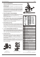
17) RE MOTE SHUT DOWN (RSD)
A volt age of +4 V...+12 V on the Re mote Shut Down in put on the
pro gram ming con nec tor CON E will switch off the out put of the unit.
It is also pos si ble to use a re lay con tact or a switch to shut the unit
down (see fig. 3 - 11).
In standby mode the power sup ply con sumes very lit tle power.
18) IN TER LOCK
The In ter lock con nec tor (CON A, rear panel) has 2 in puts which
have to be con nected to gether to turn on the out put of the unit.
As soon as the link be tween the 2 in puts of the In ter lock con nec tor
is dis rupted, the out put of the unit shuts down.
It can be used in com bi na tion with a cab i net door con tact (safety
pre cau tion) or as an emer gency break to stop a mo tor which is
pow ered by the unit.
In case the link is dis rupted the RSD LED will light. In con trast with
Re mote Shut Down, also the DCF LED will be on, the DCF sta tus
will be high and the re lay con tact will change.
Once the in puts are con nected again, the out put will be on.
No volt age may be ap plied to the pins in the In ter lock connector.
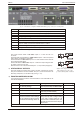
19) PRO GRAMMING SPEED
The rise and fall time is mea sured with a step wave form at the CV
prog. in put. Pro gram ming from a low to a high out put volt age is
nearly load in de pend ent, but pro gram ming down to a low volt age
takes more time on lighter loads. This is caused by the out put ca -
pac i tors, which can only be dis charged by the load be cause the
power sup ply can not sink cur rent. With the Power Sink op tion,
also the pro gram ming down speed is nearly load in de pend ent.
When hav ing a unit with a fast pro gram ming op tion, the rise and
fall time is 5 to 25 times faster (see datasheet). The pro gram ming
source must be float ing or oth er wise an ISO AMP CARD must be
used, a non-float ing source will re sult in slope dis tor tion.
When us ing fast pro gram ming it is gen er ally not rec om mended to
use re mote sens ing or se rial / par al lel op er a tion. Con sult fac tory for
ad vice. Note that the output rip ple is higher.
20) PUL SATING LOAD
To avoid over heat ing the out put ca pac i tors, the AC com po nent of
the load cur rent should be lim ited (see fig. 3 - 12).
One method of de creas ing the AC cur rent through the out put ca -
pac i tor is by us ing a large ex ter nal elec tro lytic ca pac i tor in par al lel
with the load. Care must be taken so that the ca pac i tor in com bi na -
tion with the lead in duc tance will not form a se ries res o nant cir cuit!
When us ing re mote sens ing on a pul sat ing load (for in stance a
DC-mo tor), use a ca pac i tor in se ries with a re sis tor over the load
(see fig. 3 - 13). Like this the AC-com po nent caused by the pul sat -
ing of the load is fil tered.
Note: in case of a pul sat ing load, the I mon i tor volt age will not ex -
actly match the out put cur rent. This is mainly caused by the cur rent
through the out put ca pac i tors. Re mote sens ing will worsen this ef -
fect.
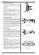
21) IN SU LA TION
For safety the in su la tion of the sep a rat ing com po nents (trans form -
ers) be tween in put and out put is tested at 3750 Vrms dur ing 1 min -
ute. This is tested be fore as sem bly.
Warn ing! The 3750 Vrms can not be tested af ter wards on the
as sem bled unit be cause the in su la tion be tween the com po nents
on the in put side to the case (like the bridge rec ti fier) is spec i fied at
2500 Vrms. Since the in su la tion out put - case is low (only 600 V DC)
the in su la tion of the pri mary com po nents to case will break down
when 3750 Vrms is ap plied be tween in put and out put (2500 Vrms +
600 VDC < 3750 Vrms) (see also fig. 3 - 14).
Note: when test ing the in su la tion, take care to charge and dis -
charge the ca pac i tors be tween in put - case and out put - case
slowly (e.g. in one sec ond). This to prevent high peak cur rents,
which could de stroy the power sup ply. Make sure to dis charge the
ca pac i tors com pletely be fore us ing it again.
fig. 3 - 11
Re mote Shut Down us ing a re lay contact
fig. 3 - 12
Pul sating load current
fig. 3 - 13
Re mote sens ing on a pul sat ing load
fig. 3 - 14
In su la tion test voltages