
Datasheet


SM6000 DELTA ELEKTRONIKA BV
July 2003, rev. March 2012 DESCRIPTIONS Page 3 - 3
The Cur rent Con trol Sta tus or CC-status out put is "1" when the unit is in
CC-mode.
The Power Sink Over Load Sta tus or PSOL-status out put is "1" when the op tional
Power Sink is over loaded or over heated.
The AC-Fail Sta tus or ACF-sta tus out put is "1" in case of Phase Loss or when the
in put volt age is be low 340 V.
The DC-Fail Sta tus or DCF-sta tus out put is "1" when the out put volt age is ei ther
5% be low or above the set point.
When the unit is in CC-mode, DCF will al ways be "1", see pre vi ous para graph 7).
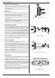
15) STATUS RE LAY OUT PUTS
The power sup ply has 2 sta tus re lay out puts, with each a change-over con tact.
They are con nected to con nec tor CON D. The pins 1,2,3 are con nected to the
DCF-relay and pins 4,5,6 to the ACF-re lay (see fig. 3 - 10).
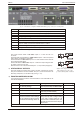
16) FUNC TION SWITCHES ON SW1
In the fol low ing ta ble the func tions of the DIP switches 1-5 of switch SW1 at the
rear side are ex plained:
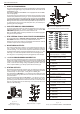
fig. 3 - 8 Location of out put ter mi nals and an a log prog. con nec tor on rear panel
Switch no. UP po si tion DOWN po si tion De fault Set ting
SW 1 - 1 Pro gramming via 15pole con nec -
tor CON E (an a log).
Op tional pro gram ming with e.g.
PSC-232, PSC-488, ISO AMP CARD
Up
SW 1 - 2 ‘Out put On’ af ter mains on ‘Out put Off’ af ter mains on Down
SW 1 - 3 DCF LED enabled DCF LED dis abled (DCF sta tus and
DCF re lay are still en abled)
Up
SW 1 - 4 Par al lel Mas ter / Slave operation Se ries Mas ter / Slave operation Up
SW 1 - 5* Af ter switch ing mains on, the unit
will start with the same set tings
for the volt age and the cur rent as
it had be fore switch ing mains off
Af ter switch ing mains on, the unit will
al ways start up with a volt age set ting
of 0 V and a cur rent set ting of 0 A.
Once the unit is switched on, the volt -
age and cur rent can be set to the pre -
ferred value.
Down
* = SW1-5 only on SM300-20 / SM600-10 and on units with op tional dig i tal encoders (op tion P220).
CON A In ter lock Con nec tor
CON B Mas ter connector for Mas ter / Slave op er a tion (out put)
CON C Slave con nec tor for Mas ter / Slave op er a tion (in put)
CON D Re lay Out puts, con tacts 1 - 6
CON E An a log Pro gram ming Con nec tor ( not avail able on SM300-20 / SM600-10, see CON H)
CON F PSC-232, from PC or pre vi ous PSC (op tional)
CON G PSC-232, to next PSC (op tional)
CON H PSC-488 (op tional) or ISO AMP CARD (op tional)
SM300-20 / SM600-10 stan dard with ISO-AMP in stead of CON E.
SW 1 Var i ous set tings, see para graph 16)
SW 2 Set tings for PSC-488 and PSC-232 (op tional) or
fig. 3 - 9 Connectors and switches on the rear panel
fig. 3 - 10
Sta tus re lay out puts on CON D.
This sit u a tion gives the re lay
po si tions dur ing fault con di tion.