
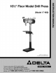
Manual


ASSEMBLY
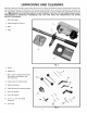
1. Assemble column (A) Fig. 4, to base (B) using four 1-
3/4" long screws (C), three of which are shown. Loosely
thread locking lever (D) into table mounting bracket (E),
as shown. Loosely thread remaining locking lever (F) Fig.
5, into split of table mounting bracket (E).
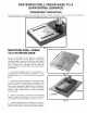
2. Insert table (G) Fig. 5, into table mounting bracket Fig. 4
(E) and tighten lever (U)to lock table in position. Tighten
locking lever (F) Fig. 5, to lock table raising mechanism
on the column.
3. Assemble table raising and lowering handle (H) Fig.
5, to table mounting bracket (E). Align the set screw on ...............
handle (H) with the flat on the shaft extending from the
mounting bracket and tighten securely with the 3mm
hex wrench supplied with the tool.
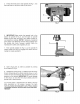
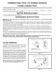
4. Carefully position drill press head (J)Fig. 6, onto
column (A) as far as it will go. Align drill press head (J)
Fig. 6, and table (G)Fig. 5, with the base of the drill
press, which was assembled in STEP 1, and tighten
locking lever (K)and set screws (L)with the 5mm hex
wrench (M) supplied.
Fig. 5
Fig. 6
5