(Model 17-925) (Model 17-990X) MODEL 17-925 PART NO. A10354 - 04-06-05 Copyright © 2005 Delta Machinery To learn more about DELTA MACHINERY visit our website at: www.deltamachinery.com. For Parts, Service, Warranty or other Assistance, please call 1-800-223-7278 (In Canada call 1-800-463-3582).
TABLE OF CONTENTS IMPORTANT SAFETY INSTRUCTIONS . . . . . . . . . . . . . . . . . . . . . . . . . . . . . . . . . . . . . . . . . . . . . . . . . . . . . . . . . . .2 SAFETY GUIDELINES . . . . . . . . . . . . . . . . . . . . . . . . . . . . . . . . . . . . . . . . . . . . . . . . . . . . . . . . . . . . . . . . . . . . . . . .3 GENERAL SAFETY RULES . . . . . . . . . . . . . . . . . . . . . . . . . . . . . . . . . . . . . . . . . . . . . . . . . . . . . . . . . . . . . . . . . . . .
SAFETY GUIDELINES - DEFINITIONS It is important for you to read and understand this manual. The information it contains relates to protecting YOUR SAFETY and PREVENTING PROBLEMS. The symbols below are used to help you recognize this information. Indicates an imminently hazardous situation which, if not avoided, will result in death or serious injury. Indicates a potentially hazardous situation which, if not avoided, could result in death or serious injury.
GENERAL SAFETY RULES READ AND UNDERSTAND ALL WARNINGS AND OPERATING INSTRUCTIONS BEFORE USING THIS EQUIPMENT. Failure to follow all instructions listed below, may result in electric shock, fire, and/or serious personal injury or property damage. IMPORTANT SAFETY INSTRUCTIONS 1. FOR YOUR OWN SAFETY, READ THE INSTRUCTION MANUAL BEFORE OPERATING THE MACHINE. Learning the machine’s application, limitations, and specific hazards will greatly minimize the possibility of accidents and injury. 2.
ADDITIONAL SPECIFIC SAFETY RULES FAILURE TO FOLLOW THESE RULES MAY RESULT IN SERIOUS PERSONAL INJURY. 1. 2. 3. 4. 5. 6. 7. 8. 9. 10. 11. 12. DO NOT OPERATE THIS MACHINE until it is completely assembled and installed according to the instructions. A machine incorrectly assembled can cause serious injury. OBTAIN ADVICE from your supervisor, instructor, or another qualified person if you are not thoroughly familiar with the operation of this machine. Knowledge is safety.
GROUNDING INSTRUCTIONS THIS MACHINE MUST BE GROUNDED WHILE IN USE TO PROTECT THE OPERATOR FROM ELECTRIC SHOCK. 1. All grounded, cord-connected machines: 2. Grounded, cord-connected machines intended for use on a supply circuit having a nominal rating less than 150 volts: In the event of a malfunction or breakdown, grounding provides a path of least resistance for electric current to reduce the risk of electric shock.
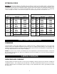
EXTENSION CORDS Use proper extension cords. Make sure your extension cord is in good condition and is a 3-wire extension cord which has a 3-prong grounding type plug and matching receptacle which will accept the machine’s plug. When using an extension cord, be sure to use one heavy enough to carry the current of the machine. An undersized cord will cause a drop in line voltage, resulting in loss of power and overheating. Fig. D-1 or D-2, shows the correct gauge to use depending on the cord length.
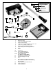
15 16 1 17 18 7 4 5 6 3 2 8 10 9 11A 11B 14 12 1. 2. 3. 4. 5. 6. 7. 8. 9. 10. 11A. 11B. 12. 13. 14. 15. 16. 17. 18.
internal gear in the table bracket. ASSEMBLY ASSEMBLY TOOLS REQUIRED 3mm Hex Wrench (Supplied) 5mm Hex Wrench (Supplied) Adjustable Wrench ASSEMBLY TIME ESTIMATE The assembly time for this unit is approximately 1-2 hours. For your own safety, do not connect the machine to the power source until the machine is completely assembled and you read and understand the entire instruction manual. 1. Attach the column (A) Fig.
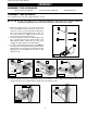
D E 5. Re-install the ring (E) Fig. 9 (removed in STEP 1). IMPORTANT: DO NOT push the ring (E) Fig. 9 all the way down on the the raising rack (F). Make certain that the top of the raising rack (F) is under the bottom of the ring (E) and that enough clearance is available to allow the rack (F) to rotate around the column. Tighten the set screw (D) with the supplied 3mm wrench. S Fig. 9 6. 7. 8. 9. Attach the table adjusting handle (K) Fig.
IMPORTANT: Make certain that the spindle taper (Q) Fig. 16 and the tapered hole in the chuck (R) are clean and free of any grease, lacquer, or rust-preventive coatings. NOTE: Household oven cleaner can effectively remove any substance from the spindle and chuck. Carefully follow the manufacturer's safety rules concerning its use. IMPORTANT: Open the chuck jaws as wide as possible with the chuck jaws inside the chuck. 13. Hold the chuck on the taper of the spindle.
5. Thread the two speed-changing levers (W) Fig. 22 into the speed changing hub. 6. Thread the speed range-changing lever (X) Fig. 23 into the hub. Fig. 22 Fig. 23 MOUNTING DRILL PRESS ON A SUPPORTING SURFACE If, during operation, the machine has a tendency to tip over, slide, or walk on the supporting surface, secure the machine base to the supporting surface with an M8x1.25x125mm carriage head screw, 8.5mm flat washer, 8.5mm lock washer, M8x1.25 hex nut through the two holes (A) Fig.
OPERATION OPERATIONAL CONTROLS AND ADJUSTMENTS STARTING AND STOPPING THE DRILL PRESS 1. 2. The on/off switches (A and B) Fig. 27 are located on the front of the drill press. To turn the machine “ON”, depress the “START” switch. To turn the machine “OFF”, depress the “STOP” switch. Make sure that the switch is in the “OFF” position before plugging in the power cord. In the event of a power failure, depress the “STOP” switch. An accidental start-up can cause injury.
VARIABLE SPEED CONTROL Turn variable speed pilot-wheel handles (A) Fig. 32 ONLY WHEN THE MOTOR IS RUNNING. Turn the pilot-wheel handles (A) clockwise to increase speed and counter-clockwise to decrease speed. The pointer (B) indicates the speed of the drill press. SPEED RANGE CONTROL Turn the speed-range control lever (A) Fig. 33 ONLY WHEN THE MOTOR IS RUNNING. The handle (A) in the “HIGH” position produces a speed range of 500 to 3200 RPM.
The sliding fit of the quill was adjusted at the factory. After a long period of time, “play” between the quill and head casting may develop. To re-adjust, loosen the nut (F) Fig. 36 and tighten the screw (E) Fig. 35 with the supplied hex wrench. After adjustment, hold the screw (E) Fig. 36, and tighten the nut (F) Fig. 36. Check the sliding fit by moving the quill up and down several times to be sure the quill does not bind. F Fig.
INSTALLING AND REMOVING DRILL BITS D NOTE: Use drill bits with a shank of 1/2" or less in diameter. DISCONNECT MACHINE FROM POWER SOURCE. B A Fig. 39 C 1. Insert the smooth end of drill bit (A) Fig. 39 in the chuck (B) as far as it will go, and then back the bit out 1/16" (or up to the flutes for small bits). 2. Center the drill bit (A) Fig. 39 in the chuck (B) before tightening the chuck with the key (C). 3. Turn the chuck key (C) Fig.
TROUBLESHOOTING For assistance with your machine, visit our website at www.deltamachinery.com for a list of service centers or call the DELTA Machinery help line at 1-800-223-7278 (In Canada call 1-800-463-3582). MAINTENANCE LUBRICATION B A Oil the variable speed pulleys and the speed range shifter mechanism weekly. Use a few drops of light machine oil in the two oil holes (A) Fig. 38, located on top of the variable speed pulleys, and the hole (B), located on top of the shifter mechanism.
KEEP MACHINE CLEAN LUBRICATION Periodically blow out all air passages with dry compressed air. All plastic parts should be cleaned with a soft damp cloth. NEVER use solvents to clean plastic parts. They could possibly dissolve or otherwise damage the material. Apply household floor paste wax to the machine table and extension table or other work surface weekly.
WARRANTY Two Year Limited New Product Warranty Delta will repair or replace, at its expense and at its option, any new Delta machine, machine part, or machine accessory which in normal use has proven to be defective in workmanship or material, provided that the customer returns the product prepaid to a Delta factory service center or authorized service station with proof of purchase of the product within two years and provides Delta with reasonable opportunity to verify the alleged defect by inspection.
PORTER-CABLE • DELTA SERVICE CENTERS (CENTROS DE SERVICIO DE PORTER-CABLE • DELTA) Parts and Repair Service for Porter-Cable • Delta Machinery are Available at These Locations (Obtenga Refaccion de Partes o Servicio para su Herramienta en los Siguientes Centros de Porter-Cable • Delta) ARIZONA Phoenix 85013-2906 4501 N. 7th Ave.