
Instruction manual


10
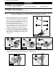
5. Re-install the ring (E) Fig. 9 (removed in STEP 1).
IMPORTANT: DO NOT push the ring (E) Fig. 9 all the way down
on the the raising rack (F). Make certain that the top of the raising
rack (F) is under the bottom of the ring (E) and that enough
clearance is available to allow the rack (F) to rotate around the
column. Tighten the set screw (D) with the supplied 3mm wrench.
Fig. 9
E
D
S
6. Attach the table adjusting handle (K) Fig. 10 to the worm gear shaft (G) and tighten the screw (L) against the flat
on the shaft with the supplied 3mm wrench.
7. Thread the clamp handle (M) Fig. 11 into the hole in the rear of the table bracket.
8. Insert the table (P) Fig. 12 into the hole in the table bracket.
9. Thread the table lock lever (Q) Fig. 13 into the hole in the front of table bracket.
L
K
G
M
P
Q
Fig. 13
Fig. 12
10. Place the drill press head (N) Fig. 14 on the column. Align the head (N) Fig. 15 to the table (C) and the base (D),
and tighten the two head-locking screws (O) Fig. 14 with the supplied 5mm wrench.
Fig. 14
Fig. 15
Fig. 10
Fig. 11
N
O
N
C
D