Instructions – Parts List Automatic Delta Spray HVLP Spray Guns 309030D 100 psi (0.7 MPa, 7 bar) Maximum Working Fluid Pressure 100 psi (0.7 MPa, 7 bar) Maximum Working Air Pressure 43 psi (300 kPa, 3.0 bar) Maximum Compliant Inbound Air Pressure Read warnings and instructions. Table of Contents Symbols . . . . . . . . . . . . . . . . . . . . . . . . . . . . . . . . . . . . . . 2 Warnings . . . . . . . . . . . . . . . . . . . . . . . . . . . . . . . . . . . . . . 2 Selection Charts . . . . . . . . . .
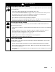
Symbols Warning Symbol Caution Symbol WARNING CAUTION This symbol alerts you to the possibility of serious injury or death if you do not follow the instructions. This symbol alerts you to the possibility of damage to or destruction of equipment if you do not follow the instructions. WARNING EQUIPMENT MISUSE HAZARD INSTRUCTIONS Equipment misuse can cause the equipment to rupture, malfunction or start unexpectedly and result in serious injury. This equipment is for professional use only.
WARNING PRESSURIZED EQUIPMENT HAZARD Spray from the gun, hose leaks or ruptured components can splash fluid in the eyes or on the skin and cause serious injury. Do not stop or deflect fluid leaks with your hand, body, glove or rag. Follow the Pressure Relief Procedure on page 13 when: you are instructed to relieve pressure; stop spraying; clean, check or service the equipment; and install or clean fluid nozzles. Do not point the spray gun at anyone or at any part of the body.
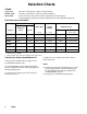
Selection Charts TERMS: Light Fluid: Up to 18 seconds with No. 2 Zahn cup (20 centipoise) Medium Fluid: 19 to 28 seconds with No. 2 Zahn cup (20–64 centipoise) Heavy Fluid: Greater than 28 seconds with No. 2 Zahn cup (greater than 64 centipoise) -2.8 Volatile Organic Compounds, High-solid Polyurethanes, Heavy Waterborne Enamels HVLP Spray Gun Assemblies Gun Assy. Part No. * Includes: Needle/ Nozzle Kit Air Cap Part No. Part No. Orifice Size Pattern Length in. (mm) in.
Air Flow and Atomizing Pressure NOTE: All tests were completed with the 0.055 in. (1.397 mm) nozzle and Part No. 195304 Air Cap, and equivalent gun inlet pressure applied to the atomization and fan ports (or fan adjustment valve fully open on manifold 243950).
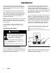
Installation The Delta Spray HVLP spray gun was designed to produce the highest quality finish with today’s fluids as well as the Low V.O.C. (volatile organic compound) fluids of tomorrow. This spray gun can spray most coatings or finishes currently being used for automotive, industrial, aerospace, marine, wood, plastic and architectural applications, while easily operating from paint delivery systems such as pressure pots or remote pumps for production line operation.
Installation Mount the Gun To mount the gun on a reciprocating arm [0.5 in. (13 mm) diameter maximum], insert the bar (A) through the hole in the manifold as shown in Fig. 2. Secure the gun to the bar by tightening the mounting screw (B). The tip of the gun should be 6 to 8 inches (150 to 200 mm) from the surface of the object being sprayed. To mount the gun on a stationary support, see Fig. 3. Also refer to the Mounting Hole Layout on page 29. Attach the gun to the support with two M5 x 0.8 capscrews (C).
Setup 1. Connect the Air Line 2. Connect the Fluid Hose NOTE: NOTE: You must install an air pressure regulator (F) on each gun air line to control air pressure to the gun. See Fig. 4. Before connecting the fluid line, blow it out with air and flush it with solvent. Use solvent which is compatible with the fluid to be sprayed. If your regulated air source does not have a filter, install an air filter (G) on each air line to ensure a dry, clean air supply to the gun.
Setup KEY N P R S T 3. Flush the Spray Gun. Cylinder Air Inlet: accepts 1/4 in. (6.3 mm) O.D. tubing Atomization Air Inlet: 1/4–18.6 npsm Fan Air Inlet: 1/4–18.6 npsm Fluid Inlet: 3/8–18.6 npsm Fluid Outlet (circulating gun only): 3/8–18.6 npsm Before putting any paint through the spray gun, flush the gun out with a solvent that is compatible with the fluid to be sprayed, using the lowest possible fluid pressure and a grounded metal container.
Setup 6. Adjust the Spray Pattern WARNING COMPONENT RUPTURE HAZARD Do not exceed the 100 psi (0.7 MPa, 7 bar) maximum fluid and air pressure of this gun. Higher pressures can cause parts to rupture and result in serious injury. Follow these steps to establish the correct fluid flow and air flow: A. Adjust the fluid flow using the fluid pressure regulator (L) installed in the gun fluid line. Typical industrial flow rates will vary with regulator pressures from 5 to 30 psi (34 to 210 kPa, 0.3 to 2.1 bar).
Setup C. Test the spray pattern and atomization while keeping the gun a consistent distance, about 6 to 8 inches (150 to 200 mm), from the test piece. D. If the spray pattern is too wide, reduce the fan air pressure (or slightly close the fan adjustment valve on manifold 243950). NOTE: Reducing the fan air pressure to 0 psi (or fully closing the fan adjustment valve) will produce a round pattern. E. Check the atomization quality again.
Notes 12 309030
Operation Pressure Relief Procedure WARNING PRESSURIZED EQUIPMENT HAZARD The system pressure must be manually relieved to prevent the system from starting or spraying accidentally. To reduce the risk of an injury from accidental spray from the gun, splashing fluid, or moving parts, follow the Pressure Relief Procedure whenever you: are instructed to relieve the pressure, stop spraying, check or service any of the system equipment, or install or clean the spray nozzle. 1.
Daily Gun Care, Flushing, and Cleaning WARNING CAUTION PRESSURIZED EQUIPMENT HAZARD To reduce the risk of a serious injury whenever you are instructed to relieve pressure, follow the Pressure Relief Procedure on page 13. Clean all parts with a non-conductive solvent, compatible with the fluid being sprayed. Conductive solvents can cause the gun to malfunction.
Daily Gun Care, Flushing, and Cleaning WARNING PRESSURIZED EQUIPMENT HAZARD To reduce the risk of a serious injury whenever you are instructed to relieve pressure, follow the Pressure Relief Procedure on page 13. 1. Relieve the pressure. 2. Shut off the gun fan and atomizing air. Fig. 11 02007 3. Supply a compatible solvent to the gun fluid inlet. 11. With the gun pointed down, clean the front of the gun, using the soft-bristle brush and solvent. 4.
Troubleshooting WARNING PRESSURIZED EQUIPMENT HAZARD To reduce the risk of a serious injury, follow the Pressure Relief Procedure on page 13 before checking or repairing any part of the gun or system. NOTE: Check all possible remedies in the troubleshooting charts before disassembling the gun. Some improper patterns are caused by the improper balance between air and fluid. Refer to Spray Pattern Troubleshooting, on page 19.
Troubleshooting General Troubleshooting (continued) Problem Cause Solution Fluid needle will not trigger. Loose or missing fluid needle stop (29) or setscrew (30). Replace stop (29) or tighten setscrew (30). Air leaking around piston (3). Replace o-ring (8) or piston (3). Swollen piston o-ring (8). Replace o-ring (8). Do not immerse piston in solvent. Insufficient air pressure on the trigger. Increase the air pressure or clean the air line. Fluid does not shut off.
Notes 18 309030
Troubleshooting Spray Pattern Troubleshooting WARNING PRESSURIZED EQUIPMENT HAZARD To reduce the risk of a serious injury, follow the Pressure Relief Procedure on page 13 before checking or repairing any part of the gun or system. PROBLEM Fluid flow is fluttering while spraying CAUSE SOLUTION Fluid nozzle not tight enough Tighten fluid nozzle to 125–135 in-lb (14–15 N m). Fluid filter clogged Check fluid filter. Air hose size is too restricted for higher air flow being used Use 5/16 in. (7.9 mm) I.
Service Items Needed for Service 1/16 in. Hex Wrench – provided Adjustable Wrench Pliers Lubricant part no. 111265; see Accessories, page 28, to order Compatible Solvent 23 Fluid Packings Replacement 24, 25 WARNING PRESSURIZED EQUIPMENT HAZARD To reduce the risk of a serious injury, follow the Pressure Relief Procedure on page 13 before checking or repairing any part of the gun or system. 9397A Fig. 13 5. Remove the piston cap (4) from the piston housing (1). Remove the springs (6, 7). 6.
Service 23 25 1 2 2 15* 1 12* 9* 2 10* 11* 3 T 3 4 29 4 24 5a 9 5 3 17 16 8 3 3 3 3 8* 6 7 30 7 6 9390A SERVICE NOTES: Cutaway View; Part No. 241745 Gun Shown 1 Torque to 145–155 in-lb (16.4–17.5 N m) 2 Lubricate threads with anti-seize lubricant 3 Lubricate with light-weight oil 4 Tighten cap (4) until it bottoms out 5 Torque to 65 in-lb (7.3 N m) 6 Apply semi-permanent anaerobic sealant. 7 Torque to 4–5 in-lb (0.45–0.56 N m) 8 Torque to 95–105 in-lb (10.
Service Reassembly 1. Non-circulating guns only: Lubricate the backup (20 ) and o-ring (21 ) and install them on the fluid outlet port plug (19). Install the plug in the fluid outlet port of the fluid housing (2). See Fig. 15. 2. All guns: Reinstall the gasket (22) in the fluid housing (2). 3. Install the o-rings (8*, 9*) on the piston (3). Install two o-rings (10*, 11*) on each of the piston stems (T). Lubricate all the o-rings, the piston, and the piston stems. 4.
Service SERVICE NOTES: 1 Torque to 145–155 in-lb (16.4–17.5 N m) 2 Lubricate threads with anti-seize lubricant 3 Lubricate with light-weight oil 4 Tighten cap (4) until it bottoms out 5 Torque to 65 in-lb (7.3 N m) 13 15* 8 14 6 Apply semi-permanent anaerobic sealant 7 Torque to 4–5 in-lb (0.45–0.56 N m) 8 Torque to 95–105 in-lb (10.7–11.8 N m) 9 Apply semi-permanent anaerobic sealant to two threads at the end of the needle shaft.
Parts Part No. 241745 to 241752, Series A Automatic HVLP Spray Gun Includes items 1–30 Ref. No. Part No. 1 2 3 4 5 195317 195221 240895 192453 See Table 5a 6 7 8* 9* 10* 11* 12* 13 14 15* 16 Description Qty. HOUSING, piston HOUSING, fluid; stainless steel PISTON CAP, piston NEEDLE ASSEMBLY; includes item 5a See Table . NEEDLE TIP 114139 SPRING, compression 114138 SPRING, compression 115066 O-RING; 1.568 in. (40 mm) OD; fluoroelastomer 111450 O-RING; 0.373 in. (9.
Parts 13 15* 17 14 16 5 2 23 21 20 5a 24 22 25 19 4 6 7 30 8* 3 13 29 5 (Ref) 9* 11* 10* *12 Exploded View; Part No.
Parts Use Only Genuine Graco Parts and Accessories Part No. 241696, Series A Manifold with bottom fluid ports Ref. No. Part No. Description 101 103 241695 113208 105 107 114246 195224 MANIFOLD, bottom fluid ports FITTING, tube, air inlet; 1/4 in. (6.3 mm) OD tube x 1/8 npt(m) SCREW, set; 5/16; 0.437 in. long NIPPLE, reducing; stainless steel; 3/8–18.6 straight pipe thread x 1/4 npt NIPPLE, air line; 1/4”–18.
Parts Use Only Genuine Graco Parts and Accessories Part No. 241697, Series A Part No. 243950, Series A Manifold with side fluid ports Manifold with side fluid ports and fan adjustment valve Ref. No. Ref. No. Part No. Description 101 103 239892 113208 105 107 114246 195224 108 180191 109 101970 110 115335 MANIFOLD, side fluid ports FITTING, tube, air inlet; 1/4 in. (6.3 mm) OD tube x 1/8 npt(m) SCREW, set; 5/16; 0.437 in. long NIPPLE, reducing; stainless steel; 3/8–18.
Accessories Cleaning Brush 105749 For use in cleaning gun Lubricant 111265 One 4 oz. (113 gram) tube sanitary (non-silicone) lubricant for fluid seals and wear areas. Fluid Whip Hose Assembly 239622 100 psi (0.7 MPa, 7 bar) Maximum Working Pressure Eases gun movement with increased hose flexibility. 4 ft. (1.22 m) long, 3/16 in. (4.76 mm) I.D., 3/8 npsm(fbe), nylon with polyurethane cover Whip Hose Parts Breakdown Part No.
Dimensions Part No. 241697 Manifold Shown 5.3 in. (134.6 mm) 2.0 in. (50.8 mm) 3.0 in. (76.2 mm) 9399A 9401A Mounting Hole Layout 0.805 in. (20.5 mm) 0.4 in. (10.2 mm) Two M5 x 0.8 x 0.25 in. (6.3 mm) holes 0.187 in. (4.8 mm) 1.750 in. (44.5 mm) 1.375 in. (35 mm) 2.125 in. (54 mm) Two 0.128 diameter x 0.31 in. (7.
Technical Data Maximum working fluid pressure . . . . . . . . . . . . . . . . . . . 100 psi (0.7 MPa, 7 bar) Maximum working air pressure . . . . . . . . . . . . . . . . . . . . 100 psi (0.7 MPa, 7 bar) Maximum compliant inbound air pressure (HVLP) . . . . 43 psi (300 kPa, 3 bar) Maximum working fluid temperature . . . . . . . . . . . . . . . 120 F (49 C) Minimum air cylinder actuation pressure . . . . . . . . . . . . 50 psi (0.34 MPa, 3.4 bar) Weight . . . . . . . . . . . . . . . . . . . . . .
Notes 309030 31
Graco Standard Warranty Graco warrants all equipment manufactured by Graco and bearing its name to be free from defects in material and workmanship on the date of sale by an authorized Graco distributor to the original purchaser for use. With the exception of any special, extended, or limited warranty published by Graco, Graco will, for a period of twelve months from the date of sale, repair or replace any part of the equipment determined by Graco to be defective.