
Technical data


10 309030
Setup
6. Adjust the Spray Pattern
WARNING
COMPONENT RUPTURE HAZARD
Do not exceed the 100 psi (0.7 MPa,
7 bar) maximum fluid and air pres-
sure of this gun. Higher pressures can cause parts
to rupture and result in serious injury.
Follow these steps to establish the correct fluid flow
and air flow:
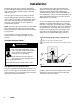
A. Adjust the fluid flow using the fluid pressure
regulator (L) installed in the gun fluid line. Typical
industrial flow rates will vary with regulator pres-
sures from 5 to 30 psi (34 to 210 kPa, 0.3 to
2.1 bar).
Fig. 8
L
7019A
NOTE: A larger fluid nozzle at a reduced fluid pressure
will maintain the same flow rate, but slow down the
fluid stream (velocity). When air is applied, this allows
the air to act on the fluid longer and improve the atom-
ization.
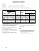
B. Using the air pressure regulator (F), set the fan
and atomizing air supply pressure at about 50 psi
(345 kPa, 3.4 bar). On manifolds 241696 and
241697, the fan and atomization air must be sup-
plied and regulated separately. On manifold
243950, one air line supplies both atomization and
fan air. Adjust the pattern length and shape by al-
tering fan air pressure (or adjusting the fan adjust-
ment valve on manifold 243950). Refer to the
Pressure Drop Chart on page 11 for the regulator
setting vs gun inlet pressure.
If available, use the fluid manufacturer’s recom-
mendations to set the air line pressure for high vol-
ume, low pressure, spray gun application.
NOTE: Local laws may limit the maximum pres-
sure to 10 psi (70 kPa, 0.7 bar) at the air cap for
HVLP compliance. 43 psi (300 kPa, 3.0 bar) inlet
air yields 10 psi (70 kPa, 0.7 bar) at the air cap.
Fig. 9
F
01997
Continued on page 11.