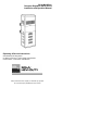
50 Hz Mini/Micro Computer Regulator (MCR) Series Installation and Operation Manual Operating & Service Instructions Sola Minicomputer Regulators UL White Card Listed – Power Supply Classification CSA Certified – Transformer Classification Contact Technical Services at (800) 377-4384 with any questions.
50 Hz Mini/Micro Computer Regulator (MCR) Series Installation and Operation Manual General Description and Specifications The Sola Micro/Minicomputer regulator provides voltage regulation and isolation from both transverse and common mode noises for any type of load. It also suppresses transients, protects from overloads and serves as a portable dedicated line. It is the ultimate in AC power conditioning equipment. Two types of units are manufactured.
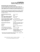
50 Hz Mini/Micro Computer Regulator (MCR) Series Installation and Operation Manual Safety Notice High voltages are present inside all regulators. Do not reach inside a unit when it is energized. To measure voltage, de-energize the unit, connect the meter, and then re-energize the unit. Hardwired Units Installation – Mechanical Table 1 shows the physical dimensions of the hardwired units. These units can be mounted with the “This Side Up” designation upwards, or they can be mounted horizontally.
50 Hz Mini/Micro Computer Regulator (MCR) Series Installation and Operation Manual Table 1. Hardwired Regulator Dimensions VA Catalog Number Outline Drawing Dim. A (cm) Dim. B (cm) Dim. C (cm) Dim. D (cm) Approx. Shipping Weight (kg) 125 63-23-612-8 A 23,11 18,90 11,43 13,67 8,08 250 63-23-625-8 A 26,92 18,90 11,43 13,67 12,24 500 63-23-650-8 A 33,66 16,21 19,69 22.
0 Hz Mini/Micro Computer Regulator (MCR) Series Installation and Operation Manual Figure 1: Hardwired Regulator Dimensions (Refer to Table 1). Knockout locations are typical. Outline A Outline B Outline C Table 2 shows the recommended bolt size for mounting the hardwired units. Table 2.
50 Hz Mini/Micro Computer Regulator (MCR) Series Installation and Operation Manual Table 3. Portable Regulator Dimensions VA Dim. A (cm) Dim. B (cm) Dim. C (cm) Approx.
50 Hz Mini/Micro Computer Regulator (MCR) Series Installation and Operation Manual Table 4. Wire and Jumper Configurations Unit (VA) 250 to 5000 Input Volts Input Terminals 90-130 H1-H4 180-260 H1-H4 (H2-H3) 310-450 H1-H5 (H2-H3) 180-260 H1-H5 (H1-H3) (H2-H5) 310-450 H1-H4 (H2-H3) 180-260 H1-H4 (H2-H3) H1-H5 (H2-H3) 7500 10000 to 15000 Jumper Connection (H1-H3) (H2-H4) Output Connection (All Models) 110-X1-X2 or X2-X3 120 X4-X2 or X2-X5 220-X1-X3 240 X4-X5 Figure 3.
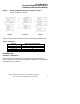
50 Hz Mini/Micro Computer Regulator (MCR) Series Installation and Operation Manual Table 5. Recommended Wire Gauges and Fusing Catalog Number Rated Volts 63-23-612-8 63-23-625-8 63-23-650-8 63-23-710-8 63-23-720-8 63-23-730-8 63-23-750-8 110-120 220-240 380-415 110-120 220-240 380-415 110-120 220-240 380-415 110-120 220-240 380-415 110-120 220-240 380-415 110-120 220-240 380-415 110-120 220-240 380-415 Min. Gauge Req.
50 Hz Mini/Micro Computer Regulator (MCR) Series Installation and Operation Manual Other Considerations for Hardwired Units Three Phase Operation If operation from a three phase source is required, three hardwired regulators may be wired in delta as shown in Figure 4. Note Required branch circuit protection must be located in the primary of each regulator, not in the three phase line. The outputs must supply three independent single phase loads of the same voltage rating.
50 Hz Mini/Micro Computer Regulator (MCR) Series Installation and Operation Manual Figure 4. Three Phase Connections A: Isolated, Single Phase Loads B: Separate, Single Phase Loads in Grounded Wye *Connect per Table 4 Contact Technical Services at (800) 377-4384 with any questions.
50 Hz Mini/Micro Computer Regulator (MCR) Series Installation and Operation Manual Installation-Electrical Portable Regulators These units are equipped with one input off/on switch and one three-wire, earthing-type input cord. The installer must add the plug ends required for use. Figure 5 shows the portable regulators schematically. Color codes for the supplied line cords are as follows: Brown- Hot Blue- Neutral Green/Yellow – Earth Or Black- Hot White- Neutral Green- Earth Figure 5.
50 Hz Mini/Micro Computer Regulator (MCR) Series Installation and Operation Manual 2000 VA There is a switch on the front of the portable regulators that allows the selection of either 220 or 240VAC output. Note The unit must not be powered while operating this switch. Unplug the unit from the power source before using this switch. Contact Technical Services at (800) 377-4384 with any questions.
50 Hz Mini/Micro Computer Regulator (MCR) Series Installation and Operation Manual Physical Characteristics of Operation – All Units Operating Temperature Standard units are designed to operate in ambient temperatures of -20°C to +50°C. In operation, a temperature rise will occur whether or not the transformer is serving a load. Normally, this rise may fall anywhere in the range of 45-100°C. depending on the regulator type and rating.
50 Hz Mini/Micro Computer Regulator (MCR) Series Installation and Operation Manual Use with Switchmode Power Supplies If a CVS transformer is used as a source for a switchmode power supply, a slight amount of ringing may be noticed on the sinewave output of the CVS at half cycle intervals for a short duration. This ringing occurs at the point when the switchmode power supply current demand drops to zero. The ringing should not be a cause for concern since it is of relatively low magnitude and frequency.
50 Hz Mini/Micro Computer Regulator (MCR) Series Installation and Operation Manual Operation on Motor Loads Because of the current-limiting effect described above, special attention should be given to motor applications. In general, the regulator must have a load rating nearly equal to the maximum power drawn during the starting cycle. This may run from two to either times the normal (running) rating of the motor. In doubtful cases, it is advisable to measure the actual starting current.
50 Hz Mini/Micro Computer Regulator (MCR) Series Installation and Operation Manual E. No Output Voltage 1. Check power source beakers or fuses. 2. Check input switch (on portable units). 3. Check continuity between input terminals, and also between output terminals. F. Transformer Operating Temperature 1. The transformer used in these regulators is designed to operate at high flux density, and hence, relatively high temperatures.
50 Hz Mini/Micro Computer Regulator (MCR) Series Installation and Operation Manual Field Replacement of Capacitors Capacitors used in all regulators are of the highest commercial grade. Nevertheless, there is a certain small percentage of failure. The Sola/Hevi-Duty limited warranty includes free replacement of any capacitor unit that fails within five years of sale. Older units can be replaced for a moderate charge.
50 Hz Mini/Micro Computer Regulator (MCR) Series Installation and Operation Manual Return Policy Most instances of initial failure to operate properly can be remedied through a telephone conversation between the user and Technical Service. If it is determined that a product must be returned, contact your local Sola/HeviDuty distributor for a Return Authorization. If the distributor is unknown, contact Customer Service at (800) 377-4384 for instructions.