(Model 23-840) PART NO. 900466 (011) Copyright © 2001 Delta Machinery To learn more about DELTA MACHINERY visit our website at: www.deltamachinery.com. For Parts, Service, Warranty or other Assistance, please call ESPAÑOL: PÁGINA 13 1-800-223-7278 (In Canada call 1-800-463-3582).
SAFETY RULES Woodworking can be dangerous if safe and proper operating procedures are not followed. As with all machinery, there are certain hazards involved with the operation of the product. Using the machine with respect and caution will considerably lessen the possibility of personal injury. However, if normal safety precautions are overlooked or ignored, personal injury to the operator may result.
ADDITIONAL SAFETY RULES FOR GRINDERS 1. DO NOT OPERATE your tool until it is completely assembled and installed according to the instructions. 15. STAND to one side of the wheel when turning on the power. 2. IF YOU ARE NOT thoroughly familiar with the operation of grinders, obtain advice from your supervisor, instructor or other qualified person. 16. AVOID awkward hand positions where a sudden slip could cause a hand to move into the grinding wheel. 17.
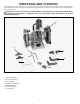
UNPACKING AND CLEANING Carefully unpack the tool and all loose items from the carton. Remove the protective coating from all unpainted parts. This coating may be removed with a soft cloth moistened with kerosene (do not use acetone, gasoline, or lacquer thinner for this purpose). WARNING: FOR YOUR OWN SAFETY, DO NOT CONNECT THE GRINDER TO THE POWER SOURCE UNTIL THE MACHINE IS COMPLETELY ASSEMBLED AND YOU HAVE READ AND UNDERSTAND THE ENTIRE INSTRUCTION MANUAL. 1 2 7 4 6 3 5 Fig.1 1. 2. 3. 4. 5. 6. 7.
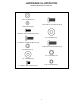
HARDWARE ILLUSTRATION Hardware Illustrated in actual size. 3/16" Flat Washer (4) 5/16-18x5/8" Hex Head Screw (4) #10-24 Hex Nut (4) #10-24x1/2" Round Head Screw (4) 3/8" Flat Washer (4) 1/4-20x3/4" Carriage Head Screw (2) 5/16-18x3/4" Hex Head Screw (2) 1/4-20 Hex Nut (2) 3/8" Lock Washer (4) 1/4" Flat Washer (2) 5/16" Lock Washer (2) 1/4-20x1/4" Hex Head Screw (2) Fig.
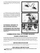
ASSEMBLY ASSEMBLING TOOL RESTS A 1. Assemble adjustable tool rest (A) Fig. 3, to left side of tool rest arm (B), as shown, and fasten with one 5/1618x3/4" hex head screw and 3/8" lockwasher (C). Assemble the remaining tool rest to the right side of the other tool rest arm in the same manner. Do not completely tighten hardware at this time. C B 2. Assemble left tool rest assembly (D) Fig.
2. Insert the short end of mounting rod (F) Fig. 7, into hole of frame (B) and fasten in place with 1/4-20x3/4" carriage head screw (G), 5/16" lock washer (H), and 1/4-20 hex nut (I). G H F B I Fig. 7 3. Assemble long end of eye shield mounting rod (F) Fig. 8, to the side of each wheel guard using bracket (J), 3/8" lockwasher, and locking knob (L). The eye shield (A) is fully adjustable so it can be put in any position by moving the shield (A) or loosening locking knob (L) and repositioning rod (F).
1. All grounded, cord-connected tools: In the event of a malfunction or breakdown, grounding provides a path of least resistance for electric current to reduce the risk of electric shock. This tool is equipped with an electric cord having an equipment-grounding conductor and a grounding plug. The plug must be plugged into a matching outlet that is properly installed and grounded in accordance with all local codes and ordinances. 2.
FLEXIBLE LAMP A The flexible lamp operates independently of the grinder. To turn the lamp on and off, rotate switch (A) Fig. 13. WARNING: To reduce the risk of fire, use 50 watt or less, 120 volt, reflector track type light bulb (not supplied). A standard household light bulb should not be used. The reflector track type light bulb should not extend below the lamp shade. Fig. 13 STARTING AND STOPPING GRINDER The switch (A) Fig. 14, is located on the front of the grinder.
CHANGING GRINDING WHEELS When changing wheels, simply remove four screws (A) Fig. 16, and remove the side cover (B). To prevent shaft rotation, place a wedge between the grinding wheel (C) Fig. 17, and the wheel guard (D). Facing the front of the grinder: to replace the grinding wheel on the right, turn the arbor nut (E) Fig. 17, counterclockwise to loosen; clockwise to tighten the arbor nut.
OPERATIONS IMPORTANT: KEEP SPARK GUARDS AND EYE SHIELDS IN PLACE AT ALL TIMES. Fig. 18 Figures 18, 19, and 20 illustrate several typical operations that can be accomplished using the grinder. Each tool rest should be positioned a little below the center of the grinding wheel and adjusted so the edge of the tool rest is as close as possible to the grinding wheel for maximum support to the piece that is being ground.This is the most practical and safest position for general work.
ACCESSORIES A complete line of accessories is available from your Delta Supplier, Porter-Cable Delta Factory Service Centers, and Delta Authorized Service Stations. Please visit our Web Site www.deltamachinery.com for a catalog or for the name of your nearest supplier. WARNING: Since accessories, other than those offered by Delta, have not been tested with this product, use of such accessories could be hazardous. For safest operation, only Delta recommended accessories should be used with this product.