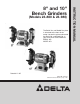
(Models 23-880 & 23-980) The Serial No. and Model No. plate is attached to the front of the motor. Locate this plate and record the Serial No. and Model No. in your manual for future reference. SERIAL NO. MODEL NO. Dated 8-11-95 PART NO. 1345338 © Delta International Machinery Corp.
SAFETY RULES Woodworking can be dangerous if safe and proper operating procedures are not followed. As with all machinery, there are certain hazards involved with the operation of the product. Using the machine with respect and caution will considerably lessen the possiblity of personal injury. However, if normal safety precautions are overlooked or ignored, personal injury to the operator may result.
ADDITIONAL SAFETY RULES FOR GRINDERS 1. WARNING: Do not operate your grinder until it is completely assembled and installed according to the 15. AVOID awkward hand positions where a sudden slip could cause a hand to move into the grinding wheel. instructions. 16. ALWAYS keep hands and fingers away from the grinding wheel. 2. IF YOU ARE NOT thoroughly familiar with the operation of grinders, obtain advice from your supervisor, instructor or other qualified person. 3.
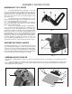
ASSEMBLY INSTRUCTIONS ASSEMBLING TOOL RESTS 1. Assemble adjustable tool rest (A) Fig. 1, to left side of tool rest arm (B), as shown, and fasten with one 3/4 inchlong hex head screw and lockwasher (C). Assemble the remaining tool rest to the right side of the other tool rest arm in the same manner. Do not completely tighten hardware at this time. 2. Assemble left tool rest assembly (D) Fig. 2, to the inside of left wheel guard (E), and fasten with two 5/8 inchlong screws and flat washers (F) as shown. 3.
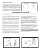
2. Insert the short end of mounting rod (F) Fig. 5, into hole of frame (B) and fasten in place with 3/4 inch-long square necked round head screw (G) and nut (H). 3. Assemble long end of eye shield mounting rod (F) Fig. 6, to the side of each wheel guard using bracket (J), lockwasher and locking knob (L). The eye shield (A) is fully adjustable so it can be put in any position by moving the shield (A) or loosening locking knob (L) and repositioning rod (F). Fig. 5 Fig. 7 Fig.
EXTENSION CORDS Use proper extension cords. Make sure your extension cord is in good condition and is a 3-wire extension cord which has a 3-prong grounding type plug and a 3-pole receptacle which will accept the tool’s plug. When using an extension cord, be sure to use one heavy enough to carry the current of the grinder. An undersized cord will cause a drop in line voltage, resulting in loss of power and over-heating. Fig. 7A shows the correct gage to use depending on the cord length.
STARTING AND STOPPING GRINDER The switch (A) Fig. 10, is located on the front of the grinder. To turn the grinder “ON” push the left hand portion of the switch and to turn the grinder “OFF” push the right hand portion of the switch. Fig. 10 DRESSING A GRINDING WHEEL When dressing a grinding wheel use a suitable silicon carbide stick type dresser, as shown in Fig. 11.
Delta Building Trades and Home Shop Machinery Two Year Limited Warranty Delta will repair or replace, at its expense and at its option, any Delta machine, machine part, or machine accessory which in normal use has proven to be defective in workmanship or material, provided that the customer returns the product prepaid to a Delta factory service center or authorized service station with proof of purchase of the product within two years and provides Delta with reasonable opportunity to verify the alleged defe