9" Bench Band Saw (Model 28-150) PART NO.
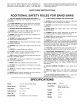
SAFETY RULES Woodworking can be dangerous if safe and proper operating procedures are not followed. As with all machinery, there are certain hazards involved with the operation of the product. Using the machine with respect and caution will considerably lessen the possibility of personal injury. However, if normal safety precautions are overlooked or ignored, personal injury to the operator may result.
Your risk from these exposures varies, depending on how often you do this type of work. To reduce your exposure to these chemicals: work in a well ventilated area, and work with approved safety equipment, such as those dust masks that are specially designed to filter out microscopic particles. SAVE THESE iNSTRUCTiONS ADDITIONAL SAFETY RULES FOR BAND SAWS 1. DO NOT OPERATE YOUR BAND SAW UNTIL it is completely assembled and installed according to the instructions. 2.
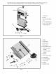
Yournewbandsawis shippedcompleteinonecontainer, Carefullyunpackthesawandallloose itemsfromthe shippingcontainer.Figs.2 and3 illustratethe contentsof the container. 1 - Band Saw 2 - Lamp 3 - Lamp cord clamps (2) 4 - 1/4" Iockwashers (2) 5 - M6 x 12mm cheese head screws (2) 2 Fig, 2 6 - Table 7 - Miter gage 8 -M6 wing nut 6 9 - Flat washer 10 - M6 x 30mm screw 11 - 4mm Hex socket wrench 12 - 3mm Hex socket wrench 17 \ 13 - Pointer \ 14 -M5 x lOmm screw 15 - Flat washer 16 - Lever assembly 17 - Pini
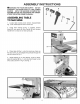
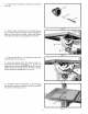
ASSEMBLY iNSTRUCTiONS _WARNING: FOR YOUR OWN SAFETY, DO NOT CONNECT THE BAND SAW TO THE POWER SOURCE UNTIL THE MACHINE IS COMPLETELY ASSEMBLED AND YOU HAVE READ AND UNDERSTOOD THE ENTIRE OWNER'S MANUAL. ASSEMBLING TO MACHINE TABLE 1. Locate table locking lever (shown disassembled) Fig. 4, flat washer (B) and 4mm wrench (C). 2. Using 4mm wrench (C)Fig. 4, supplied, remove screw (D) and spring (E) from handle (A) and remove handle from nut (G). Do not lose spring (E). Fig. 4 H 3. Place table (H) Fig.
5. Locatepinionknob(N)Fig.9,spring(O),andspecial screw(P). Fig.9 6. Positionpinionknob(N)Fig.10, ontothe backof sawsothattheteethonthe pinionknob(N)engagethe teeth on the trunnion(R).Fastenin placewith special screw(P)andspringusingthesupplied4mmwrench. Fig.10 7. Fastenpointer(S)Fig.11,to the backof bandsaw usingthe M5x 10mmscrew(T). 8. Usingthe supplied4mm Hex socketwrench,reassembletablelockinghandle(F)Fig.11,on studand replacescrewandspring(D).
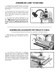
ASSEMBLING LAMP TO MACHINE 1. Assemble the lamp bracket (A) Fig. 13, to the two holes located on the back top cover of the machine using the two M6 x 12mm screws and 1/4" Iockwashers (B) as shown. 2. Peel backing from cord clamps (C)Fig. 13, and apply one clamp at each of the approximate locations shown. Make certain the lamp cord is re-routed out of the way, then secure cord (D)to cord clamps (C) as shown in Fig. 13. 3. The flexible lamp operates independently of the band saw.
FASTENING BAND SAW TO SUPPORTING SURFACE If during operation there is any tendency for the machine to tip over, slide, or "walk" on the supporting surface, the machine must be secured to the supporting surface. Four holes are provided in the band saw base for this purpose, three of which are shown at (A) Fig. 16. Fig. 16 CONNECTING BAND SAW TO POWER SOURCE POWER CONNECTIONS A separate electrical circuit should be used for your tools.
GROUNDING CAUTION: THIS TOOL MUST BE GROUNDED FROM ELECTRIC SHOCK. INSTRUCTIONS WHILE IN USE TO PROTECT THE OPERATOR In the event of a malfunction or breakdown, grounding provides a path of least resistance for electric current to reduce the risk of electric shock. This tool is equipped with an electric cord having an equipment-grounding conductor and a grounding plug. The plug must be plugged into a matching outlet that is properly installed and grounded in accordance with all local codes and ordinances.
OPERATING CONTROLS AND ADJUSTMENTS STARTING AND STOPPING SAW The switch (A) Fig. 20, is located on the front side of the band saw. To turn the saw "ON" move the switch (A) to the up position. To turn the saw "OFF" move the switch (A) to the down position. Fig. 2O LOCKING SWITCH IN THE "OFF" POSITION When the tool is not in use, the switch be locked in the "OFF" position. This can be done by grasping the switch toggle (B)Fig. 21, and pulling it out of the switch, as shown.
ADJUSTING BLADE TENSION Blades of 1/8", 1/4", and 3/8" wide by 59-1/2" in length are available for use with your band saw. NOTE: The blade tension must be adjusted to accommodate different blade widths in order to provide proper blade tracking, cutting performance and blade life. 1. DISCONNECT THE MACHINE FROM THE POWER SOURCE. 2. After the desired blade is assembled to the two band saw wheels, turn tension knob (A) Fig. 24, clockwise until spring (B) begins to compress. Fig. 24 3.
ADJUSTING UPPER BLADE GUIDES AND BLADE SUPPORT BEARING iMPORTANT: BOTH THE UPPER AND LOWER BLADE GUIDES MUST BE PROPERLY ADJUSTED TO PREVENT THE BLADE FROM TWiSTiNG DURING OPERATION. 1. DISCONNECT THE MACHINE FROM THE POWER SOURCE. 2. NOTE: Upper blade guard (B) Fig. 27, is shown removed for clarity. 3. Loosen the two screws (C) Fig. 27, and adjust the blade guides (D) as close as possible to the sides of the saw blade, being careful not to pinch the blade.Then tighten the two screws (C). 4.
ADJUSTING LOWER BLADE GUIDES AND BLADE SUPPORT BEARING The lower blade guides and blade support bearing should be adjusted at the same time as the upper guides and support bearings as follows: 1. DISCONNECT THE MACHINE FROM THE POWER SOURCE. Fig. 29 Fig. 30 2. Loosen two screws (A) Fig. 29, and move guides (B) as close as possible to the sides of the blade, being careful not to pinch the blade between the guides. Then tighten two screws (A). 3. The front edge of guide blocks (B) Fig.
TILTING THE TABLE 1. The table can be tilted 45 degrees to the right. To tilt the table, loosen lock handle (A) Fig. 31, and turn knob (B) clockwise until desired angle is established. Then tighten lock handle (A). NOTE: The table lock handle (A) can be repositioned by pulling out on the handle and repositioning it on the nut located underneath the hub of the handle. A scale (C) and pointer (D) are provided to indicate the degree of tilt. Fig.
ADJUSTING BELT TENSION If the drive belt on your band saw needs adjustment, proceed as follows: 1. DISCONNECT SOURCE. SAW FROM THE POWER Fig. 34 2. The belt (A) Fig. 34, drives the saw pulley from the motor pulley. Correct tension of the belt (A) is when there is approximately 1/4" deflection in the center span of the belt (A) using light finger pressure. If belt tension needs adjusted, loosen two screws (B) Fig. 35, and rotate motor accordingly. Tighten screws (B) when adjustment is completed.
WRENCH STORAGE The 3mm and 4mm adjustment wrenches (A) supplied with your band saw can be conveniently stored inside the wheel cover as shown in Fig. 37. MITER GAGE A miter gage (A) Fig. 38, is supplied with your band saw. The miter gage body (C)can be adjusted up to 45 degrees right and left, by loosening lock knob (B), rotating miter gage body (C) to the desired angle, and tightening lock knob (B). Fig. 37 BLADE CHANGING To change blades, proceed as follows: 1. DISCONNECT SAW FROM THE POWER SOURCE. 2.
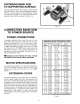
ACCESSORY RIP FENCE OPERATION AND ADJUSTMENTS The accessory rip fence (A) Fig. 42, can be moved along the table surface by lifting lock lever (B) and sliding the rip fence (A) to the desired location on the table. Push down on lever (B) to firmly lock rip fence in position on the table. When the rip fence (A) is locked to the band saw table, it should be parallel to the miter gage slot (D). If an adjustment is necessary, proceed as follows: 1. DISCONNECT SOURCE. MACHINE 2. Loosen two screws (E)Fig.
CUTTING CURVES When cutting curves, turn the stock carefully so that the blade follows without twisting. If a curve is so abrupt that it is necessary to repeatedly back up and cut a new kerf, a narrower blade, a blade with more set, or additional relief cuts Fig. 44, may be necessary to allow the blade to cut more efficiently. The more set a blade has, the easier it will allow the stock to be turned, but the cut is usually rougher than where a medium amount of set is used. RELIEF CUTS CUTTING Fig.
Fig.46 Fig.46 illustratesa typicalbevelcuttingoperationusinga mitergage. Fig.47 Fig.47 illustratesa typicalresawingapplicationusingtheaccessoryripfence.
TROUBLESHOOTING GUIDE in spite of how well a band saw is maintained, problems can occur. The following troubleshooting guide will help you solve the more common problems: Trouble: SAW WILL NOT START. Probable Cause Remedy 1. Saw not plugged in. 1. Plug in saw. 2. Fuse blown or circuit breaker tripped. 2. Replace fuse or reset circuit breaker. 3. Cord damaged. 3. Have cord replaced. Trouble: BREAKER KICKS OUT FREQUENTLY. Probable Cause Remedy 1. Extension cord too light or too long. 1.
TROUBLESHOOTING GUIDE (CONTINUED) Trouble: BLADE WILL NOT TRACK. Probable Cause Remedy 1. Blade too loose 1. Adjust tension 2. Upper wheel not properly adjusted. 2. Adjust upper wheel. 3. Improper back-up bearing adjustment. 3. Adjust back-up. Trouble: CUT DOES NOT AGREE WITH SETTING ON THE TILT SCALE. Probable Cause Remedy 1. Pointer out of adjustment Trouble: 1. Adjust pointer. BLADE WILL NOT STAY ON WHEEL. Probable Cause Remedy 1. Blade not tensioned properly. 1.
BAND SAW BLADES A band saw blade is a delicate piece of steel that is subjected to tremendous strain. You can obtain long use from a band saw blade if you give it fair treatment. Be sure you use blades of the proper thickness, width and temper for the various types of material to be cut. Always use the widest blade possible. Use the narrow blades only for sawing small, abrupt curves and for fine, delicate work. This will save blades and will produce better work.
NOTES
L.TA All Delta Machines and accessories are manufactured to high quality standards and are serviced by a network of Porter-Cable°Delta Factory Service Centers and Delta Authorized Service Stations. To obtain additional information regarding your Delta quality product or to obtain parts, service, warranty assistance, or the location of the nearest service outlet, please call 1-888-848-5175 (In Canada call 1800-463-3582).