(Model 28-195) PART NO. 902127 (0112) Copyright © 2001 Delta Machinery To learn more about DELTA MACHINERY visit our website at: www.deltamachinery.com. For Parts, Service, Warranty or other Assistance, please call ESPAÑOL: PÁGINA 23 1-800-223-7278 (In Canada call 1-800-463-3582).
GENERAL SAFETY RULES Woodworking can be dangerous if safe and proper operating procedures are not followed. As with all machinery, there are certain hazards involved with the operation of the product. Using the machine with respect and caution will considerably lessen the possibility of personal injury. However, if normal safety precautions are overlooked or ignored, personal injury to the operator may result.
ADDITIONAL SAFETY RULES FOR BAND SAWS WARNING: FAILURE TO FOLLOW THESE RULES MAY RESULT IN SERIOUS PERSONAL INJURY. 1. 14. NEVER REACH UNDER THE TABLE while the machine is running. DO NOT OPERATE THIS MACHINE UNTIL it is assembled and installed according to the instructions. 15. TURN THE MACHINE “OFF” to back out of an uncompleted or jammed cut. 2. OBTAIN ADVICE from your supervisor, instructor, or another qualified person if you are not familiar with the operation of this tool. 16.
POWER CONNECTIONS A separate electrical circuit should be used for your machines. This circuit should not be less than #12 wire and should be protected with a 20 Amp time lag fuse. If an extension cord is used, use only 3-wire extension cords which have 3prong grounding type plugs and matching receptacle which will accept the machine’s plug.
EXTENSION CORDS Use proper extension cords. Make sure your extension cord is in good condition and is a 3-wire extension cord which has a 3-prong grounding type plug and matching receptacle which will accept the machine’s plug. When using an extension cord, be sure to use one heavy enough to carry the current of the machine. An undersized cord will cause a drop in line voltage, resulting in loss of power and overheating. Fig. D, shows the correct gauge to use depending on the cord length.
1 2 16 4 5 8 6 9 7 10 15 For Fig. 2 11 14 12 13 Fig. 2 For mounting lamp to machine 1 - Band Saw 10 - M6 x 12mm sheet metal screw (2) 2 - Table 11.
1 2 6 3 7 8 4 9 5 Fig. 3 For Fig.
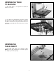
ASSEMBLY INSTRUCTIONS WARNING: FOR YOUR OWN SAFETY, DO NOT CONNECT THE MACHINE TO THE POWER SOURCE UNTIL THE MACHINE IS COMPLETELY ASSEMBLED AND YOU READ AND UNDERSTAND THE ENTIRE OWNER’S MANUAL. ASSEMBLING STAND AND FEET A B 1. Assemble the stand, as shown in Fig. 4, using the 32 M8x20mm Carriage head screws, 3/8" flat washers and M8 hex nuts supplied.
ASSEMBLING TABLE TO MACHINE A 1. Slide table (A) Fig. 7, into position on band saw trunnions, as shown. Fig. 7 2. Line up the four threaded holes in bottom of table with four holes in table trunnions (B) Fig. 8, and fasten the table to the trunnions using the four M6 x 16mm hex head bolts (C) and M6 flat washers (A), three of which are shown. A A C A C B Fig. 8 ASSEMBLING TABLE INSERT 1. Place table insert (A) Fig. 9, in opening of table.
ASSEMBLING TABLE ALIGNMENT SCREW Insert M6 x 30mm button head bolt (A) Fig. 11, down through hole in table, as shown, and place a M6 flat washer (C) onto bolt from underneath table and fasten in place with an M6 wing nut (B). A C B Fig. 11 ASSEMBLING LAMP TO MACHINE 1. Assemble the lamp bracket (A) Fig. 12, to the two holes located on the back top cover of the machine. Fasten the lamp bracket to the back top cover using two M6 x 12 sheet metal screws (B) and M6 lockwashers (C) and tighten.
OPERATING CONTROLS AND ADJUSTMENTS STARTING AND STOPPING SAW The switch (A) Fig. 17, is located on the front side of the band saw. To turn the saw “ON” move the switch (A) to the up position.To turn the saw “OFF” move the switch (A) to the down position. A LOCKING SWITCH IN THE “OFF” POSITION Fig. 17 IMPORTANT: When the machine is not in use, the switch should be locked in the “OFF” position to prevent unauthorized use. This can be done by grasping the switch toggle (B) Fig.
TRACKING THE BLADE For accurate work and maximum blade life, it is important that the blade (A) Fig. 20, be centered on the upper band saw wheel. When this adjustment is properly made, the blade will “track” – that is, it will run steady in the same line. To “track” the blade, proceed as follows: 1. DISCONNECT MACHINE FROM POWER SOURCE. 2.
ADJUSTING UPPER BLADE GUIDES AND BLADE SUPPORT BEARING The blade guides must be properly adjusted to prevent the blade from twisting during operation. The upper blade guides and blade support bearings should be adjusted only after the blade is tensioned and tracking properly. To adjust, proceed as follows: 1. DISCONNECT MACHINE FROM POWER SOURCE. 2. Remove two screws (A) Fig. 22, and remove blade guard (B) from guide assembly. B A Fig. 22 3. The upper blade guides (C) Fig.
ADJUSTING LOWER BLADE GUIDES AND BLADE SUPPORT BEARING The lower blade guides and blade support bearing should be adjusted at the same time as the upper guides and support bearing as follows: 1. DISCONNECT MACHINE FROM POWER SOURCE. E B B A A Fig. 25 F C G D Fig. 26 2. Loosen the two screws (A) Fig. 25, and move the guides (B) as close as possible to the sides of the blade, being careful not to pinch the blade between the guides. Then tighten the two screws (A). 3.
TILTING THE TABLE The table can be tilted 48 degrees to the right and approximately 3 degrees to the left. To tilt the table, loosen lock handle (A) Fig. 27, tilt the table to the desired angle and tighten lock handle (A). NOTE: The table lock handle (A) can be repositioned by pulling out on the handle and repositioning it on the nut located underneath the hub of the handle. A scale (B) and pointer (C) is provided to indicate the degree of table tilt. C A B Fig.
ADJUSTING UPPER BLADE GUIDE ASSEMBLY C The upper blade guide assembly (A) Fig. 31, should always be set about 1/8 above or as close as possible to the top surface of the workpiece being cut. Loosen lock knob (B) and rotate adjusting knob (C) to position the guide assembly (A) at the desired height. Then tighten lock knob (B). B A Fig. 31 A CHANGING BLADES A To change blades, proceed as follows: 1. DISCONNECT MACHINE FROM POWER SOURCE. 2. Pull handles (A) Fig.
MINIMUM CUTTING RADIUS Turning radius may vary depending on the type of blade and amount of set. Each blade, however, depending on its width, can cut continuously without backtracking any curve having a radius as much or more than the specified minimum turning radius of the blade, as shown in the chart (A) Fig. 35, located inside top wheel cover. A Always use the widest blade possible and limit use of narrow blades for sawing small, abrupt curves and for fine, delicate work. Fig.
WRENCH STORAGE The hex wrench (A) supplied with your band saw can be stored inside the wheel cover, as shown in Fig. 39. A Fig. 39 DUST CHUTE A dust chute (A) Fig. 40, is provided which enables you to connect your band saw to a standard shop vacuum or dust collector. The opening of the dust chute is 2-1/4" I.D. A Fig. 40 MITER GAGE A C A miter gage (A) Fig. 41, is supplied with your band saw.
ACCESSORY 28-196 RIP FENCE An ideal accessory for use with your band saw is the 28-196 Rip Fence, shown in Fig. 43. It can be moved along the table surface by loosening lock lever (A), moving the fence (B) to the desired location and tightening lock lever (A). B A Fig. 43 OPERATING THE BAND SAW Before starting the machine, see that all adjustments are properly made and the guards are in place. Turn the upper wheel by hand to make sure that everything is correct BEFORE turning on the power.
ACCESSORIES A complete line of accessories is available from your Delta Supplier, Porter-Cable • Delta Factory Service Centers, and Delta Authorized Service Stations. Please visit our Web Site www.deltamachinery.com for a catalog or for the name of your nearest supplier. WARNING: Since accessories other than those offered by Delta have not been tested with this product, use of such accessories could be hazardous. For safest operation, only Delta recommended accessories should be used with this product.
PORTER-CABLE • DELTA SERVICE CENTERS (CENTROS DE SERVICIO DE PORTER-CABLE • DELTA) Parts and Repair Service for Porter-Cable • Delta Machinery are Available at These Locations (Obtenga Refaccion de Partes o Servicio para su Herramienta en los Siguientes Centros de Porter-Cable • Delta) ARIZONA Tempe 85282 (Phoenix) 2400 West Southern Avenue Suite 105 Phone: (602) 437-1200 Fax: (602) 437-2200 CALIFORNIA Ontario 91761 (Los Angeles) 3949A East Guasti Road Phone: (909) 390-5555 Fax: (909) 390-5554 San Leandro