
Instruction manual


9
MODEL 28-206 ENCLOSED STAND ASSEMBLY
WARNING: FOR YOUR OWN SAFETY, DO NOT CONNECT THE MACHINE TO THE POWER SOURCE UNTIL
THE MACHINE IS COMPLETELY ASSEMBLED AND YOU READ AND UNDERSTAND THE ENTIRE
INSTRUCTION MANUAL.
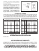
1. Place the stand top (A) Fig. 5, on a flat surface as
shown.
2. Align the two holes in the motor mounting plate (E)
Fig. 5, with the two holes (B) in the stand top (A).
3. Insert shaft (D) through the holes in the motor
mounting plate and the holes in the stand top.
4. Attach the two “C” rings (C) Fig. 5 to the shaft.
Fig. 5
A
B
E
D
C
C
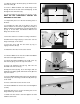
Fig. 6
5. Align the four holes on the motor bracket with the
four holes (C) Fig. 6, on the motor mounting plate.
NOTE: MAKE SURE THAT THE MOTOR PULLEY (A)
FIG. 6, IS MOUNTED ON THE SIDE WITH THE BELT
OPENING HOLE (B).
6. Insert a M8x1.25x16mm round head flange screw
through the hole in the motor bracket and the hole in the
motor mounting plate.
7. Thread a M8x1.25 hex flange nut onto the screw.
8. Repeat this process for the three remaining holes in
the motor bracket and the motor mounting plate.
A
B
C
Fig. 7
9. Align the holes in the side (A) Fig. 7, with the holes
in the stand top (B).
NOTE: MAKE SURE THAT THE HINGE CATCHES (C)
FIG. 7 ARE POINTED TOWARD THE STAND TOP (B)
AS SHOWN.
10. Insert a M8x1.25x16mm hex head flange screw
through the hole in the side of stand and through the
hole in the top of stand.
11. Thread a M8x1.25 flange nut onto the screw. NOTE:
DO NOT COMPLETELY TIGHTEN THE HARDWARE
AT THIS TIME.
12. Repeat this process for the five remaining holes in
the side and top of stand.
13. Assemble the other stand side in the same manner.
A
B
C