(Model 28-280) The Serial No./Model No. plate is attached to the right side of the base casting. Locate this plate and record the Serial No. and Model No. in your manual for future reference. SERIAL NO.___________________________________ MODEL NO. __________________________________ DATED 1-15-96 PART NO. 426-02-651-0023 ©Delta International Machinery Corp.
SAFETY RULES Woodworking can be dangerous if safe and proper operating procedures are not followed. As with all machinery, there are certain hazards involved with the operation of the product. Using the machine with respect and caution will considerably lessen the possibility of personal injury. However, if normal safety precautions are overlooked or ignored, personal injury to the operator may result.
UNPACKING AND CLEANING Carefully unpack the band saw and all loose items from the shipping container. Remove the protective coating from the machined surfaces of the band saw. This coating may be removed with a soft cloth moistened with kerosene (do not use acetone, gasoline or lacquer thinner for this purpose). After cleaning, cover all unpainted surfaces with a good quality paste wax.
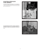
ASSEMBLING BELT AND PULLEY GUARD Assemble the belt and pulley guard (A) to the top of the stand, as shown in Fig. 6, using the two 1/4-20 x 1/2 hex head screws, washers and nuts (B). ASSEMBLING SWITCH If you purchased your band saw complete with stand and electricals, you received a switch mounted in a switch box and a cord set connected to the motor. Assemble the switch to the band saw arm as follows: Fig. 6 1. MAKE CERTAIN THE BAND SAW IS DISCONNECTED FROM THE POWER SOURCE. 2.
5. Fasten the switch box to the band saw arm using two nuts and lockwashers (A) Fig. 10, which were removed in STEP 3. A Fig. 10 6. Remove screw and cable clamp (E) Fig. 11, from lower arm of band saw. 7. Insert switch cord (F) Fig. 12, into clamp (E) which was removed in STEP 6, and fasten switch cord (F) to band saw as shown. IMPORTANT: CHECK AND MAKE CERTAIN THE ON/OFF SWITCH-TO-MOTOR CORD (F) FIG. 7, IS NOT CONTACTING MOTOR PULLEY OR BELT. ADJUST CORD (F) FIG.
TABLE INSERT Place table insert (A) Fig. 14, in the hole provided in the table, making sure the pin (B) in the table engages one of the indents in the table insert. Fig. 14 TILTING THE TABLE The table on your band saw can be tilted 45 degrees to the right and 10 degrees to the left. To tilt the table, loosen the two lock knobs (A) Fig. 15, tilt the table to the desired angle and tighten the two lock knobs (A). Fig. 15 ADJUSTING TABLE STOP The band saw is equipped with an adjustable table stop (A) Fig.
ADJUSTING BLADE TENSION On the back of the upper wheel slide bracket, there is a series of graduations. These indicate the proper tension for various widths of blades. With the blade on the wheels, turn the knob (A) Fig. 18, to raise or lower the wheel, until the red fiber washer (B) is in line with the proper graduation for the size of blade being used. The graduations will be found correct for average work, and are not affected by rebrazing of the saw blade.
ADJUSTING UPPER BLADE GUIDE ASSEMBLY The upper blade guide assembly (A) Fig. 21, should always be set as close as possible to the top surface of the material being cut by loosening lock knob (B) and moving the guide assembly (A) to the desired position. Fig. 21 The upper blade guide assembly should also be adjusted so that the blade guides (A) Fig. 22, are flat with the blade.
ADJUSTING UPPER BLADE GUIDES AND BLADE SUPPORT BEARING The upper blade guides and blade support bearings are adjusted only after the blade is tensioned and tracking properly. To adjust proceed as follows: 1. The upper blade guides (A) Fig. 23, are held in place by means of the set screws (B). Loosen the set screws (B) to move the guides (A) as close as possible to the side of the blade, being careful not to pinch the blade. Then tighten the screws (B). 2. The guides (A) Fig.