
Installation Sheet


208782 Rev. A
INSTALLATION INSTRUCTIONS
WIRING
Note: Wires connecting between box(es) and from transformer
must be protected from abrasion, and being pulled at connec-
tions. They also may have to be fished through at a later stage
of construction. Depending on installation, the cable bushings
included may be replaced by installer supplied 1/2” conduit.
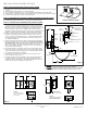
Rough-in box as per Figure 1.
The transformer is to be installed in an adjacent accessible
space. (Do NOT install the transformer inside the control
box.) Cable from the transformer to the driver board/controller
may be roughed in at this time depending on installation. Use
cable which complies to local electrical codes for a 1 amp load.
HARDWIRE OR BATTERY: If recessed box is supplied, rough
in as per Figure 1. The most vandal resistant installation is when
the control box is as close to the bottom of the sink as feasible.
For wall hung sink installation, sensor conduit rough in should
be directly under the basin to minimize sensor cord exposure.
Rough in drainage. Rough in water supply to 10” control box
inlets and to spout connection. Finish walls.
Valve spacer is for temporary use only for flushing of system.
Must be replaced with solenoid (Fig. 2).
257mm
(10.13”)
Control Box
305mm (12")
Stainless Steel
Cover Plate
102mm (4")
355mm
(14”)
max.
Fig. 1
Product supplied as
shown by solid lines.
All items shown by
dotted lines supplied
by other or Trim
Package.
208782 208782 208782 208782 208782
208782 208782 208782 208782 208782
Rough-in box
to be installed
(flush to 6mm
(1/4”)) to
finished wall
Finished
Wall
Fig. 2
061137A - Adjustment Wrench
Installation should be in accordance with local
plumbing and electrical codes.
FLUSH ALL PIPES THOROUGHLY BEFORE
INSTALLATION.
Remove suitable knockout(s) in box(es) and insert
cable bushing(s).
Fig. 3
Towards
“red dot” side
to increase
temperature
Towards “blue
dot” side to
reduce
temperature
www.specselect.com
Fasten box to
framing using
holes provided
inside of box
57mm (2.25”) Min.*
152mm
(6”)
Recommended***
19mm
(3/4”)
Max.
Sill Depth**
140mm
(5.5”)
Recommended***
Page 1
Rough-In
0 to -1/4”
NOTE: Installer/Specifier to ensure dimensions
specified for installation are followed (see Fig. 1).
NOTE: Not for use as an anti-ligature device.
* A minimum 57mm (2-1/4”) installation height above fixture rim is required unless a
greater air gap is designated by local codes/regulations.
** A maximum sill depth of 19mm (3/4”) from backsplash to sink edge is allowable.
*** It is recommended that a sink with a dimension shown in Fig. 1 be used.
Slip on spout
tube (must be
braced, i.e.
copper
strapping)
Outlet
3/8” M.I.P.
Inlets 1/2”
Copper
Hot
Cold
063136A
Thermostatic Mixing Valve (with checks)
063135A
Stops
FLUSH SYSTEM/SET TEMPERATURE
Remove coverplate from control box. Open screwdriver stop(s) to flush installation for
1 minute minimum.
A Run water for a sufficient time so the hot and cold water supplies are as hot and
cold as they will get.
B Thermostatic Mixing Valve
To adjust the mixed outlet temperature of the valve, remove the cap to gain access
to the adjusting spindle. The spindle should be rotated towards the “blue dot” side
to reduce the temperature and towards the “red dot” side to increase the temper-
ature - until the desired set point is reached (refer to Fig. 3).
Periodic Inspection/Maintenance - We recommend that this valve is checked at
least once per year to ensure its continued function. For installations with poor or
unknown water quality, or other adverse supply conditions, it may be necessary to
check the valve at more frequent intervals. The temperature should be checked at
the same outlet as was used for commissioning in the first instance. If the temper-
ature is more than 3°F from the commissioning in temperature, refer to the included
Maintenance and Installation Guide.
C Close stop(s).
300 T4328ARI
300 T4328ATR