
Installation Sheet


061210A
Sensor Plate
(Blue Ring)
060072A
Screws and
Driver Bit Kit
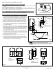
Fig. 7
Hardwire Connection
Solenoid Leads
Keyed Switch (not used)
Hardwire Battery Clip
(Note: connection already
made to converter)
Sensor Lead
060683A
Hardwire Converter
24VAC to 6VDC
Fig. 8
Controller Battery Clip
(Note: connection already made to controller)
Info Icon
LCD Display
Enter Exit Button
Up and Down Arrow
STEP 4. CONTROLLER ADJUSTMENTS
If adjustments are required. Note factory defaults for program shown in Quick Reference Chart.
Otherwise, replace the driver board housing cover as the electronic product is ready for use.
Adjustment Range
Factory Default Setting
DescriptionSelection Adjustment
0 to 8 seconds and
then 1 minute to 8
minutes
0 Seconds
The length of time water will run after
the user removes their hands from the
sensing zone.
Run-On time
3 Settings:
Fast (8 pulses/second)
Standard (4 pulses/second)
Slow (2 pulses/second)
Standard (4 pulses/second)
Response Time is the amount of time it
takes for the sensor to react to hands
placed in the sensing zone.
Response Time
1 to 8 seconds of
blocking time
1 second
The amount of time required between
uses. This prevents the faucet from
running water excessively.
Block Time
3” to 15“ (76 mm to
381 mm) from sensor
8” (203 mm) from sensor
You can set the distance at which the
sensor will detect hands in the wash area.
Sensor Range
Not Adjustable
1 minute + Run-On time
The auto timer is the length of time before
the faucet stops running in the event that
the sensor is obstructed by a foreign object.
Auto Timer
7 to 240 seconds
(if enabled)
10 seconds
Allows for continuous flow for a set amount
of time, regardless of how long an object
is placed in front of the sensor. Run-On
settings are disabled in this mode.
Metering Mode
3000T4328 CONTROLLER QUICK REFERENCE CHART
060989A
Controller
(Controller is set to 10” range, metering mode
disabled - settings are adjustable)
208782 Rev. A
www.specselect.com
Page 3
061264A
Spout Plate
57 mm (2.25”)
MIN*