(Model 31-390, 391, 392) PART NO. 406-11-651-0006 - 03-12-02 Copyright © 2002 Delta Machinery To learn more about DELTA MACHINERY visit our website at: www.deltamachinery.com. For Parts, Service, Warranty or other Assistance, please call 1-800-223-7278 (In Canada call 1-800-463-3582).
GENERAL SAFETY RULES Woodworking can be dangerous if safe and proper operating procedures are not followed. As with all machinery, there are certain hazards involved with the operation of the product. Using the machine with respect and caution will considerably lessen the possibility of personal injury. However, if normal safety precautions are overlooked or ignored, personal injury to the operator may result.
ADDITIONAL SAFETY RULES FOR ABRASIVE FINISHING MACHINES WARNING: FAILURE TO FOLLOW THESE RULES MAY RESULT IN SERIOUS PERSONAL INJURY. 1. 2. 3. 4. 5. 6. 7. 8. 9. 10. 11. 12. 13. DO NOT OPERATE THIS MACHINE UNTIL it is assembled and installed according to the instructions. OBTAIN ADVICE from your supervisor, instructor, or another qualified person if you are not familiar with the operation of this machine. FOLLOW ALL WIRING CODES and recommended electrical connections. USE THE GUARDS WHENEVER POSSIBLE.
POWER CONNECTIONS A separate electrical circuit should be used for your tools. This circuit should not be less than #12 wire and should be protected with a 20 Amp time lag fuse. If an extension cord is used, use only 3-wire extension cords which have 3prong grounding type plugs and matching receptacle which will accept the tool’s plug.
GROUNDED OUTLET BOX CURRENT CARRYING PRONGS GROUND STRIP BRING POWER LEAD T H R U ENTRANCE HOLE IN BOTTOM OF STA RTER ENCLOSURE CONNECT THREE POWER LEADS TO TERMINALS L1 - L2 - L3 AND GREEN LEAD TO T H E GROUND STRIP GROUNDING BLADE IS LONGEST OF THE 3 BLADES Fig. B Fig. A EXTENSION CORDS 31-390 ONLY: Use proper extension cords.
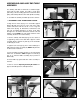
ASSEMBLY WARNING: DO NOT OPERATE THIS TOOL UNTIL YOU READ AND UNDERSTAND THE ENTIRE INSTRUCTION MANUAL. ASSEMBLING LEGS TO EDGE SANDER Carefully assemble the two support legs to the base of the edge sander as follows: A 1. Fasten each support leg (C) Fig. 3, to the base of the machine (A) with five 3/8-16 x 1" hex head screws, ten flat flatwashers, five lockwashers and hex nuts, (D) Fig. 3.
ASSEMBLING BELT TENSION LEVER Assemble the belt tension lever (A) Fig. 7, to the tensioning mechanism by threading the end of lever (B) into the tapped hole (C) and tighten lock nut. C A B Fig. 7 ASSEMBLING TOP GUARD DUST CHUTE ASSEMBLY AND B Two dust chutes (A) Fig. 8, are supplied with the top guard (B) and are equipped with four-inch diameter openings.
ASSEMBLING AUXILIARY ABRASIVE DRUM AND SPINDLE ASSEMBLY TO DRIVE PULLEY A The auxiliary abrasive drum and spindle assembly is furnished as standard equipment with the edge sander and is used for finish sanding of small contour workpieces. To assemble the abrasive drum and spindle assembly, proceed as follows: NOTE: The top guard and dust chute assembly has been removed for clarity. 1. DISCONNECT TOOL FROM POWER SOURCE. 2. Align the three holes (A) Fig.
ASSEMBLING AUXILIARY END TABLE ASSEMBLY The auxiliary end table is furnished as standard equipment with the edge sander. The table is used when performing contour sanding operations around the drive pulley and auxiliary abrasive drum and spindle assembly. C A To assemble the auxiliary end table proceed as follows: Fig. 17 1. DISCONNECT TOOL FROM POWER SOURCE. 2. Align the two holes (A) Fig.
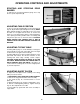
OPERATING CONTROLS AND ADJUSTMENTS STARTING AND STOPPING EDGE SANDER To start the tool, push the start button (A) Fig. 25; to stop the tool, push stop button (B). A B Fig. 25 ADJUSTING TABLE POSITION To raise or lower the straight table, loosen lock knobs (A) Fig. 26, adjust table height and tighten knobs (A). NOTE: When straight sanding, it is advisable to raise one end of the table so it is higher than the other, as shown. This allows for cooler belt running and less material burning.
ADJUSTING LONG PLATEN To adjust the long platen when sanding on the straight table: C 1. DISCONNECT TOOL FROM POWER SOURCE. 2. Remove the top guard and dust chute assembly. 3. Loosen two hex nuts (A) Fig.29 holding brackets (B) at each end of the machine, and move platen (C) in or out as needed. IMPORTANT: MAKE CERTAIN THE LONG STRAIGHT PLATEN IS NOT MOVED TOO FAR FORWARD SO THAT THE TABLE INTERFERES WITH THE SANDING BELT. A B Fig.
ADJUSTING BELT TRACKING To check and adjust the tracking of the sanding belt on the pulleys, proceed as follows: A 1. Raise the dust chutes (A) Fig. 34, at both ends of the top guard and dust chute assembly. C 2. Make certain the top guard and dust chute assembly is not interfering with the rotation of the sanding belt. B 3. Apply power to the machine. Jog the on/off switch several times and check to see if the sanding belt (B) Fig.
OPERATIONS EDGE SANDING When edge sanding, it is advisable to raise one end of the table as shown in Fig. 36. This allows cooler belt running, prevents spot wear, reduces material burning and promotes longer belt life. The table should be positioned so it is close to, but not contacting the sanding belt. CONTOUR SANDING AROUND THE DRIVE PULLEY IMPORTANT: The hinged dust chute (A) Fig. 37, must be flipped up to allow contour sanding around the drive pulley (C).
MAINTENANCE CHANGING SANDING BELTS To remove and install sanding belts, proceed as follows: 1.DISCONNECT TOOL FROM POWER SOURCE. 2. The sanding belt can be changed with or without the top guard and dust chute removed from the machine. 3. Push in on belt tension lever (A) Fig. 39, to release belt tension, and remove sanding belt (B) as shown. 4. Push in on belt tension lever (A) Fig. 39, assemble new sanding belt (B) around pulley (C) and release tension lever (A). 5.
CHANGING DRUM SPINDLES 1. IMPORTANT: DISCONNECT TOOL FROM POWER SOURCE. 2. Loosen set screw (E) Fig. 42, and remove drum spindle (F) from adapter plate (B). 3. Insert desired size of drum spindle (F) Fig. 42, into adapter plate (B) and tighten set screw (E). IMPORTANT: MAKE CERTAIN FLAT ON SPINDLE (F) IS FACING SET SCREW (E) BEFORE TIGHTENING SCREW. F B E Fig.
PORTER-CABLE • DELTA SERVICE CENTERS (CENTROS DE SERVICIO DE PORTER-CABLE • DELTA) Parts and Repair Service for Porter-Cable • Delta Machinery are Available at These Locations (Obtenga Refaccion de Partes o Servicio para su Herramienta en los Siguientes Centros de Porter-Cable • Delta) ARIZONA Tempe 85282 (Phoenix) 2400 West Southern Avenue Suite 105 Phone: (602) 437-1200 Fax: (602) 437-2200 CALIFORNIA Ontario 91761 (Los Angeles) 3949A East Guasti Road Phone: (909) 390-5555 Fax: (909) 390-5554 San Leandr